
Mixer apparatus and computer program

a technology of mixing machine and computer program, which is applied in the field of mixing machine, can solve the problems of cumbersome setting-changing operation and inability to be seen very easily, and achieve the effect of facilitating the setting operation of operators and visual identification with eas

Active Publication Date: 2006-09-28
YAMAHA CORP
View PDF4 Cites 32 Cited by
  • Summary
  • Abstract
  • Description
  • Claims
  • Application Information

AI Technical Summary

Benefits of technology

[0004] In view of the foregoing, it is an object of the present invention to provide a mixer apparatus which allows a grouping state of operators to be visually identified with ease and also facilitates setting operation of the operators, as well as a computer program therefor.
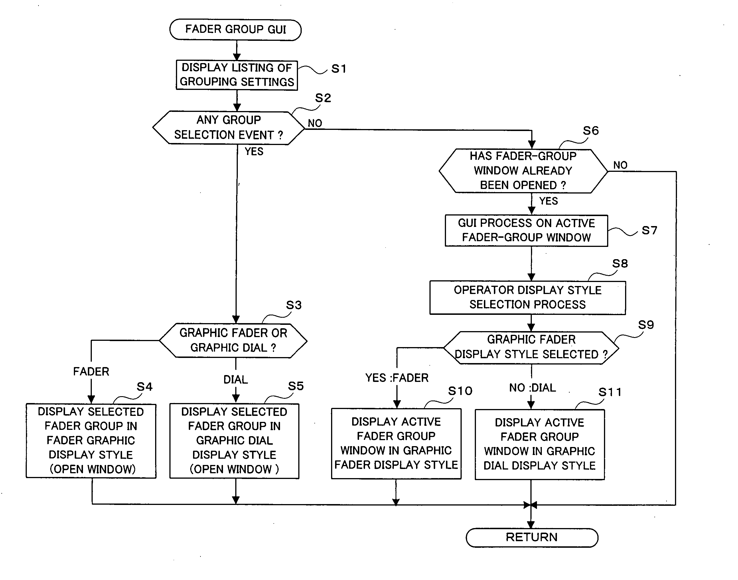
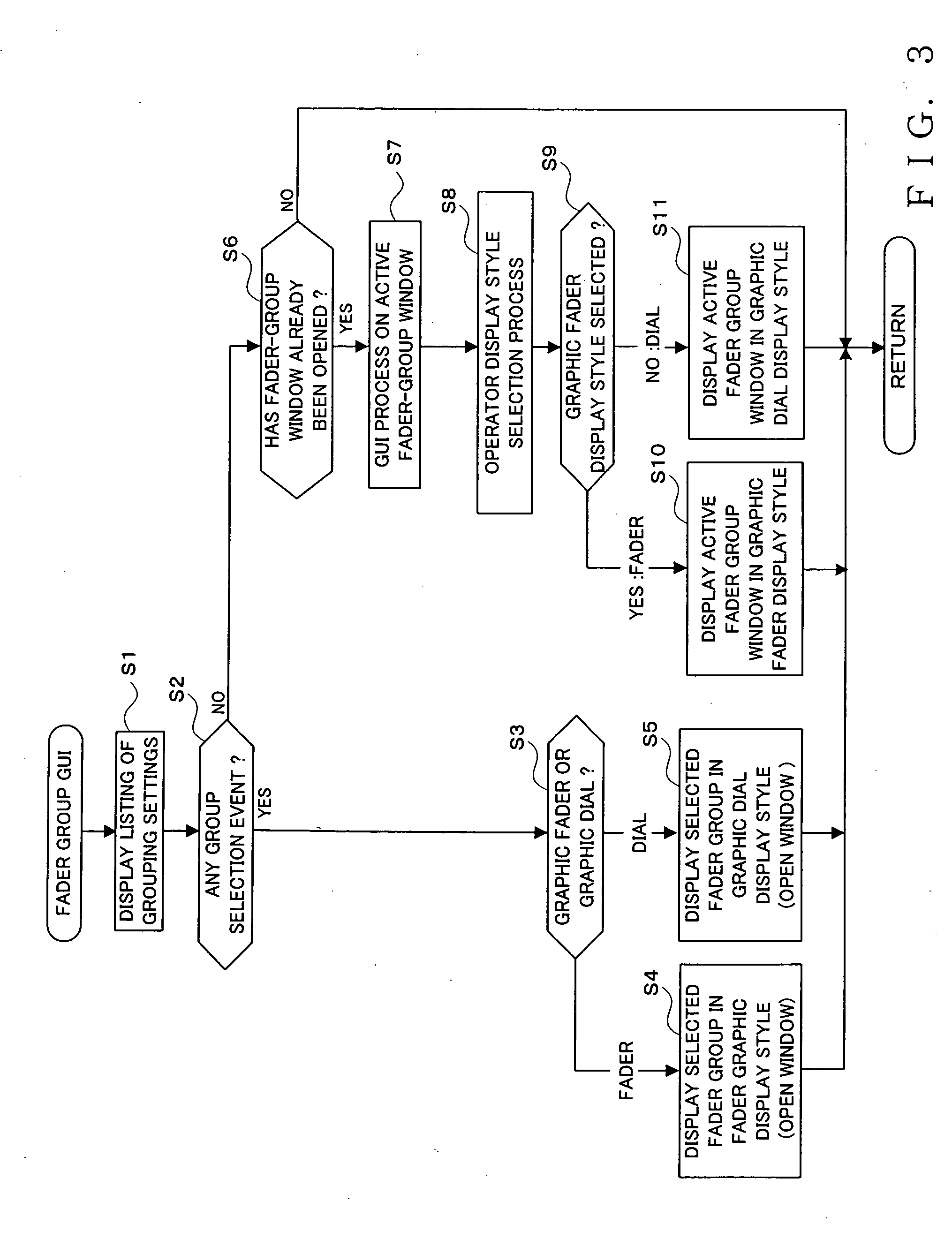
[0006] According to the present invention, a window of a given group is opened on the screen of the display in response to selection operation by the user, and thus, the grouping state of the fader operators can be identified visually with ease. Further, in response to operation by the user on the image displayed on the window of the given group and indicative of the settings of the individual fader operators belonging to the given group, an image for making a change in the settings is displayed, and the individual fader operators belonging to the given group are automatically driven, to thereby effect a change in the settings. Thus, operation of the faders can be performed on the screen, which can enhance the setting operability.

Problems solved by technology

However, in the conventionally-known mixer apparatus, the grouping settings are displayed only in a listing form and can not be viewed very easily.
Further, if a change is to be made in the settings, operators on the console have to be operated, and thus, setting-changing operation tends to be cumbersome.

Method used


Image

  • Mixer apparatus and computer program
  • Mixer apparatus and computer program
  • Mixer apparatus and computer program

Examples


Embodiment Construction

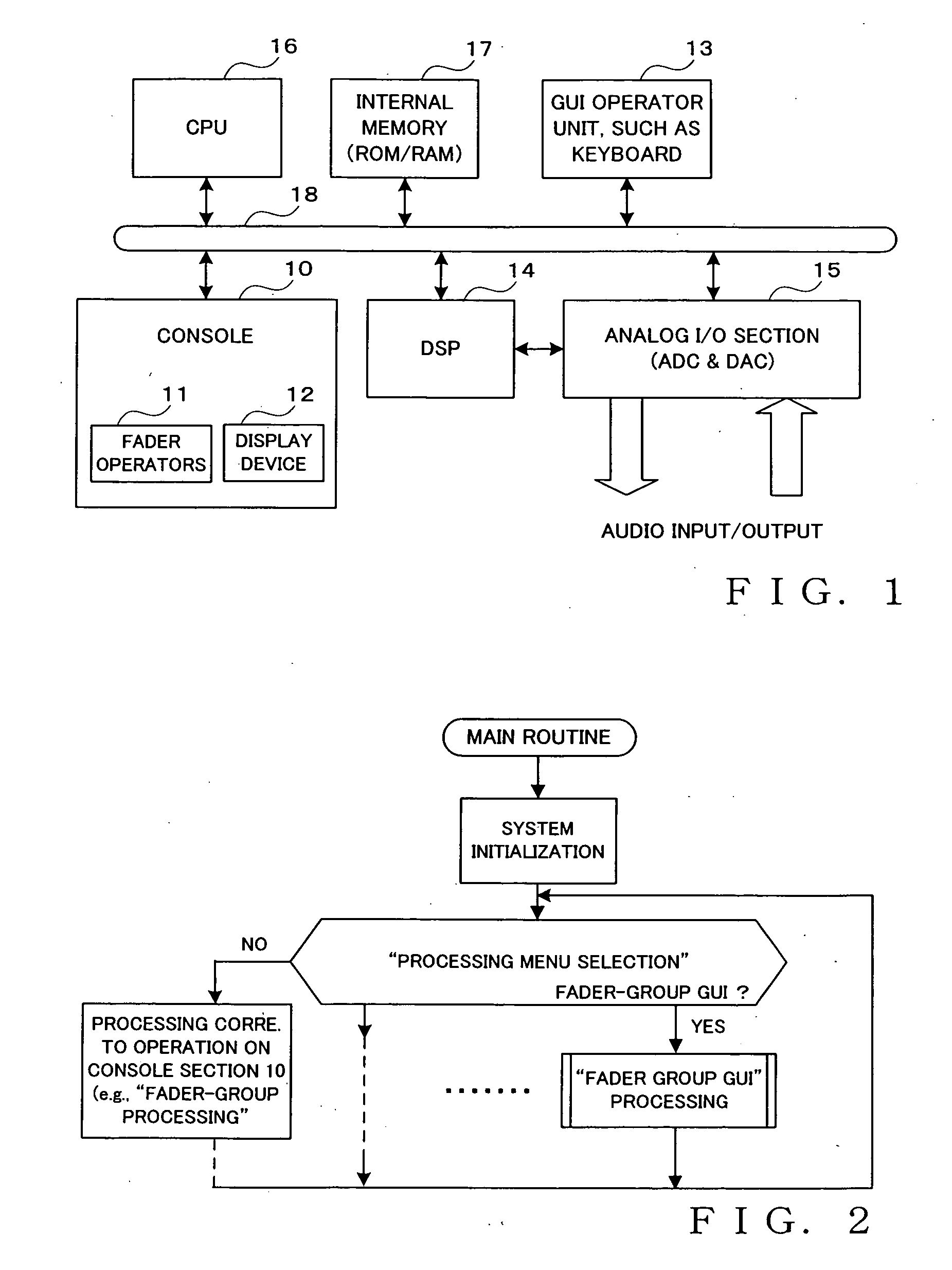
[0015]FIG. 1 is a block diagram showing an example general setup of a mixer apparatus in accordance with an embodiment of the present invention, which is, for example, in the form of a digital mixer. Similarly to the apparatus disclosed in Japanese Patent Application Laid-open No. HEI-3-58351 identified above, the mixer apparatus of FIG. 1, includes, on a console section 10, a plurality of fader operators 11 that are provided in corresponding relation to a plurality of channels and both manually operable and automatically driveable via motors or the like. These fader operators 11 are divided into one or more groups, and the fader operators 11 of each of the groups (i.e., within a same group) can be caused to operate collectively in an interlocked fashion. Although not specifically shown, the mixer apparatus of FIG. 1 includes, on the console section 10, various other conventional operators than the fader operators 11, such as grouping-related operators, and various display elements....


PUM


Abstract

Manually-operable and automatically-driveable fader operators are provided in corresponding relation to a plurality of channels, and a plurality of the fader operators are grouped in such a manner that the fader operators in a same group are operable collectively in an interlocked fashion. On a display screen, a window of a given group is opened in response to selection operation by a user, and a graphic image indicative of settings of the individual fader operators belonging to the given group is displayed. In response to operation by the user on the image displayed on the window of the given group and indicative of the settings of the individual fader operators, an image for effecting a change in the settings is displayed, and the individual fader operators belonging to the given group are automatically driven, to thereby change the settings. Such arrangements allow a grouping state of the operators to be identified visually with an increased ease and also facilitate setting operation.

Description

BACKGROUND OF THE INVENTION [0001] The present invention relates to mixer apparatus usable in various places, such as theaters, concert halls and studios, where are handled audio signals. More particularly, the present invention relates to an improved mixer apparatus in which fader operators of a plurality of channels are grouped into one or more groups so that, when necessary, the fader operators in each group can be caused to operate collectively in an interlocked fashion, and which can be operated with an enhanced operability using an image display operation technique, such as a GUI. [0002] Japanese Patent Application Laid-open Publication No. HEI-3-58351 corresponding to U.S. Pat. No. 5,054,077 discloses that fader operators of a plurality of channels are grouped into one or more groups and settings of the fader operators within each of the groups can be changed collectively in an interlocked fashion. For example, in an independent operation mode, desired settings for a given on...

Claims


Application Information

Patent Timeline
IPC IPC(8): H04B1/00H04B1/20
CPCH04H60/04
Inventor HIRANO, MASASHI
Owner YAMAHA CORP
Learn More