Method of purifying contaminated oil from particles suspended in the oil in a centrifugal separator

a centrifugal separator and oil technology, applied in the direction of centrifugal force sediment separation, separation process, centrifugal force, etc., can solve the problems of difficult removal of oil, small cases, and common contamination of oil by different kinds of particles

Active Publication Date: 2006-09-28
ALFA LAVAL CORP AB
View PDF4 Cites 13 Cited by
  • Summary
  • Abstract
  • Description
  • Claims
  • Application Information

AI Technical Summary

Benefits of technology

[0018] The method of the invention may with advantage be used for mineral oils, 20 which have been contaminated with very small particles, for example very small soot particles or metal particles which are floating in the oil and therefore do not settle. Mineral oils have usually a density of 0.85-0.90 g / cm3 at 40° C. Earlier the only possibility to purify oil containing this kind of contaminants have been to use kieselguhr or bleaching clay filters, which filter materials are expensive and create problems in connection with deposition of the used filter beds.
[0019] If the mineral oil has been used as an insulating agent in a transformer or tap changer and is free from additives apart from a necessary oxidation 30 inhibitor, the separation aid with advantage may be a liquid polymer, which binds the small soot particles that are present in the oil. Also rolling oil as well as chlorine-paraffin oil contaminated with very small metal par-tides may be cleaned in this way.

Problems solved by technology

During such use the oils commonly become contaminated by different kinds of particles.
The contaminants in the shape of particles, which are to be removed from the oil, may in many cases be very small and difficult to remove from the oil.
To separate two liquid phases of different density from each other in a centrifugal separator may cause problem if one of the phases is present only in a small amount.

Method used


Image

  • Method of purifying contaminated oil from particles suspended in the oil in a centrifugal separator
  • Method of purifying contaminated oil from particles suspended in the oil in a centrifugal separator

Examples


Embodiment Construction

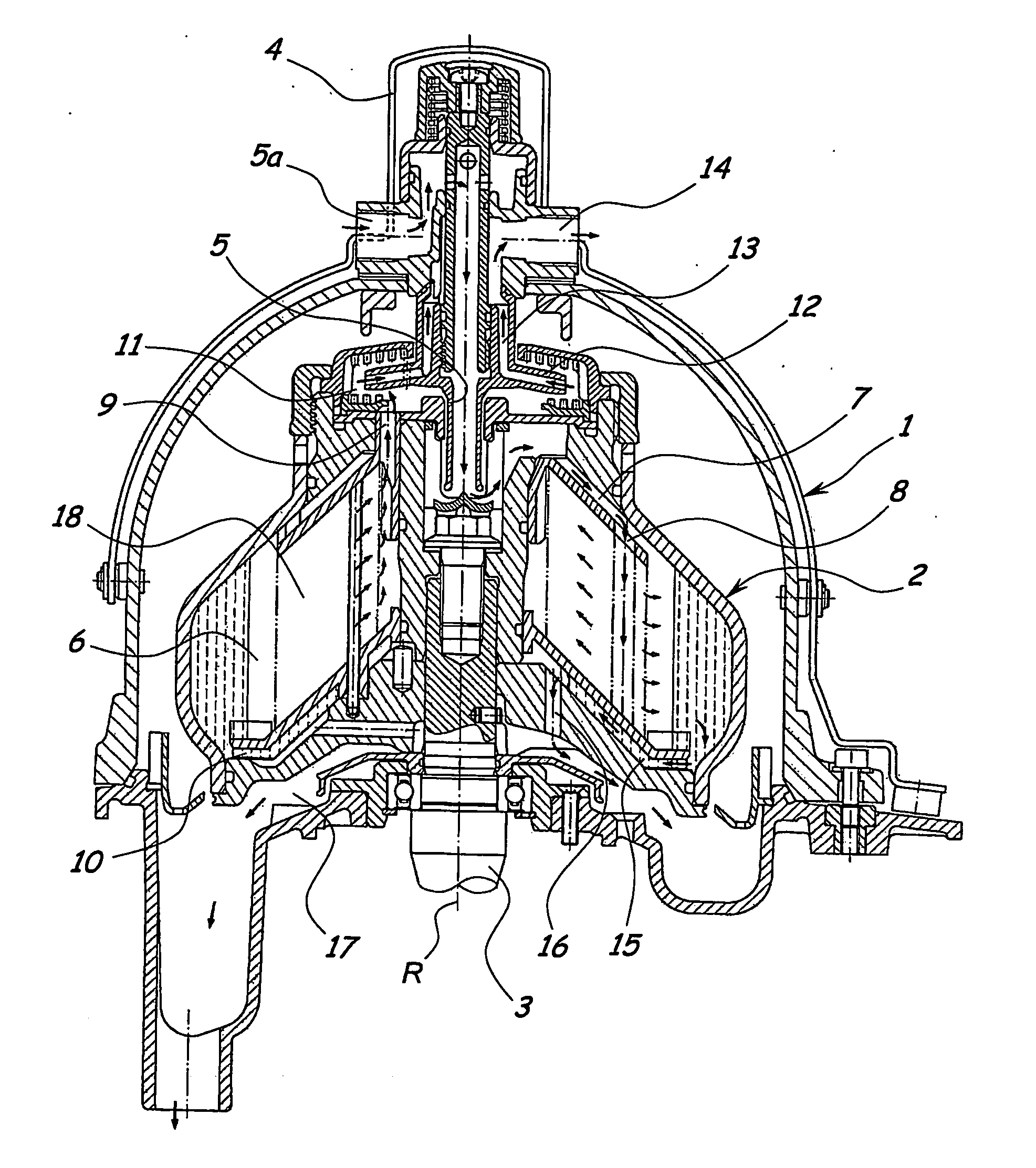
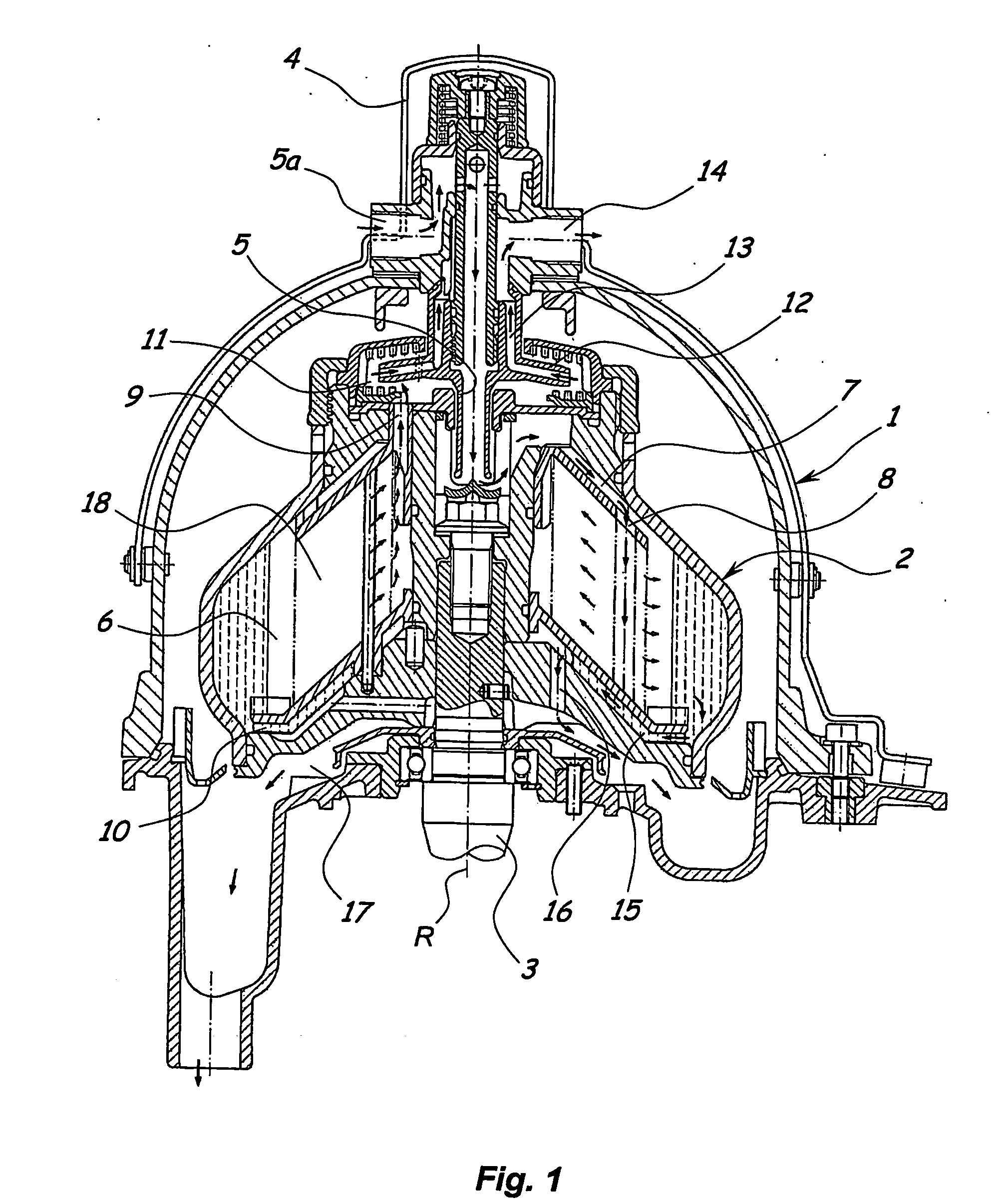
[0029] The centrifugal separator shown in the drawing has a stationary housing 1, in which there is arranged a centrifugal rotor 2 rotatable about a vertical centre axis R. The rotor 2 is mounted on top of a vertical driving shaft 3 coupled to a driving device (not shown). A connection device 4 carried by the housing 1 includes, among other things, a vertical inlet pipe 5 extending from above into the rotor 2 and forming an inlet channel that opens into a central inlet space in the rotor. Said inlet channel communicates at its upper end with an inlet 5a of the connection device 4.

[0030] The rotor 2 forms a separation chamber 6 and several inlet passages 7 leading from said central inlet space in the rotor to respective inlets 8 of the separation chamber 6. The rotor 2 also forms a central light phase outlet 9 of the separation chamber 6 at a relatively small distance from the centre axis R and, at a greater distance from the centre axis R, a number of heavy phase outlets 10 of the ...


PUM

PropertyMeasurementUnit
densityaaaaaaaaaa
densityaaaaaaaaaa
temperatureaaaaaaaaaa

Abstract

In a centrifugal separator the liquid separation aid attracts/binds contaminating particles in oil supplied to a separation chamber. Purified oil is discharged through a central light phase outlet of the separation chamber, the liquid separation aid and separated particles are discharged through a heavy phase outlet. Purification is carried through using a starting liquid, supplied to the separation chamber to form a layer that creates a liquid seal in the centrifugal rotor, covering said heavy phase outlet. Contaminated oil and liquid separation aid are supplied to the separation chamber. While purified oil leaves the separation chamber through the light phase outlet, at starting liquid and liquid separation aid together with particles are discharged through the heavy phase outlet.

Description

FIELD OF THE INVENTION [0001] The present invention relates to a method of purifying contaminated oil from particles suspended in the oil by means of a liquid separation aid, which has a density larger than that of the oil. The separation aid is dispersed in the contaminated oil in order to make the particles more easily separable from the oil. The contaminated oil and the liquid separation aid are supplied into a separation chamber of a rotating centrifugal rotor. The liquid separation aid and the particles are separated from the oil by centrifugal force. The purified oil is discharged from the separation chamber through a central light phase outlet. The separated particles and the liquid separation aid are discharged from the separation chamber through a heavy phase outlet situated radially outside of the light phase outlet. BACKGROUND OF THE INVENTION [0002] Mineral oils (also half- and full-synthetic) as well as animal oils and vegetable oils, with or without additives, are used...

Claims


Application Information

Patent Timeline
Patent Type & Authority Applications(United States)
IPC IPC(8): C10M175/02C10M175/00C10G31/10B04B1/00
CPCC10G31/10C10M175/0058Y10S494/901B04B1/08C10M175/0008C10M175/00C10M175/02
Inventor WASE, CLAES
Owner ALFA LAVAL CORP AB
Why Eureka
Try Eureka