Thermal interface material and method for making the same

a technology of thermal interface materials and making methods, applied in the direction of ohmic-resistance heating, basic electric elements, semiconductor devices, etc., can solve the problems of inadequately meeting the heat dissipation requirements of modem electronic components, and the heat conduction coefficient of thermal interface materials is now considered to be too low for many contemporary applications

Active Publication Date: 2006-10-05
TSINGHUA UNIV +1
View PDF5 Cites 45 Cited by
  • Summary
  • Abstract
  • Description
  • Claims
  • Application Information

AI Technical Summary

Problems solved by technology

However, a heat conduction coefficient of the thermal interface material is now considered to be too low for many contemporary applications, because it cannot adequately meet the heat dissipation requirements of modem electronic components.

Method used


Image

  • Thermal interface material and method for making the same
  • Thermal interface material and method for making the same
  • Thermal interface material and method for making the same

Examples


Embodiment Construction

[0020] Referring to FIG. 6, a thermal interface material 100 includes a macromolecular matrix 10 and a number of thermally conductive fibers 20 incorporated therein directionally and uniformly. The macromolecular matrix 10 includes a first surface 11 and an opposite second surface 12. Preferably, the first surface 11 is substantially parallel to the second surface 12. The thermally conductive fibers 20 are substantially parallel to each other, and extend from the first 11 to the second surface 12. Preferably, the thermally conductive fibers 20 are substantially perpendicular to the first and second surfaces 11, 12.

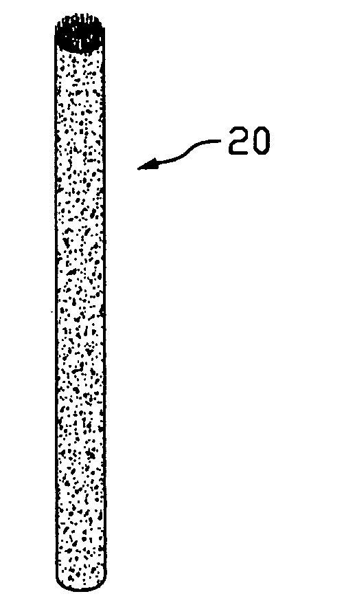
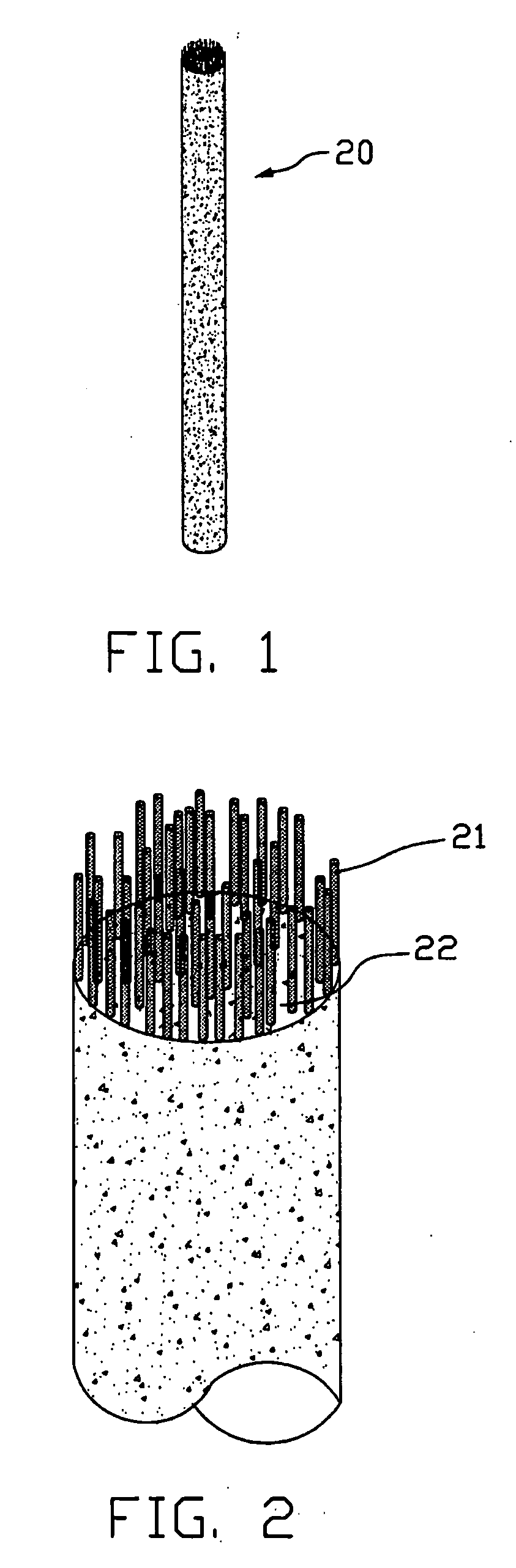
[0021] Referring to FIG. 1 and FIG. 2, the thermally conductive fibers 20 may be a composite fiber selected from the group comprised of a carbon nanotube / macromolecular material composite fiber, a metal / macromolecular composite fiber, a ceramics / macromolecular composite fiber and a carbon fiber. The carbon nanotube / macromolecular material composite fiber 20 may be made o...


PUM

PropertyMeasurementUnit
diameteraaaaaaaaaa
temperatureaaaaaaaaaa
diameteraaaaaaaaaa

Abstract

A thermal interface material (100) includes a macromolecular matrix (10) and a plurality of thermally conductive fibers (20) incorporated therein. The macromolecular matrix (10) has a first surface (11) and an opposite second surface (12). Each of the thermally conductive fibers (20) is substantially parallel to each other and extends between the first and second surfaces (11), (12). A method for manufacturing the thermal interface material includes the steps of: (a) providing a number of thermally conductive fibers; (b) aligning the thermally conductive fibers uniformly and directionally to form an array of the thermally conductive fibers; (c) immersing the array of thermally conductive fibers into a liquid macromolecular material; (d) solidifying the liquid macromolecular material to obtain a macromolecular matrix having the two opposite surfaces with the thermally conductive fibers embedded therein, that is, a desired interface material is obtained.

Description

CROSS-REFERENCE TO RELATED APPLICATIONS [0001] This application is related to three corresponding U.S. patent applications each entitled “THERMAL INTERFACE MATERIAL AND METHOD FOR MANUFACTURING SAME” with application Ser. No. 11 / 024,513, filed on Dec. 28, 2004, and “THERMAL INTERFACE MATERIAL AND METHOD FOR MANUFACTURING SAME” with application Ser. No. 11 / 089,864, filed on Mar. 25, 2005, and “THERMAL INTERFACE MATERIAL AND METHOD FOR MANUFACTURING SAME” with application Ser. No. 10 / 991,022, filed on Nov. 17, 2005, each having the same assignee as the instant application. The disclosures of the above-identified applications are incorporated herein by reference.BACKGROUND [0002] 1. Technical Field [0003] The invention relates generally to thermal interface materials and making methods thereof; and more particularly to a kind of thermal interface material which enhances contact between a heat source and a heat dissipating device, and a method for making the same. [0004] 2. Discussion o...

Claims


Application Information

Patent Timeline
Patent Type & Authority Applications(United States)
IPC IPC(8): H05B3/00H05B1/00H05B11/00
CPCH01L23/373H01L23/3733H01L2924/0002H01L2924/00
Inventor HUANG, HUALIU, CHANG-HONGFAN, SHOU-SHAN
Owner TSINGHUA UNIV
Why Eureka
Try Eureka