
Systems and methods for controlling duct pressurization for cable installation

a technology of duct pressurization and cable installation, which is applied in the direction of cables, cables laying apparatus, instruments, etc., can solve the problems of limiting the distance over which existing cable blowing techniques are applied, affecting the effect of cable installation, and high back pressure at the originating end of the du

Inactive Publication Date: 2006-10-05
VERIZON PATENT & LICENSING INC
View PDF4 Cites 39 Cited by
  • Summary
  • Abstract
  • Description
  • Claims
  • Application Information

AI Technical Summary

Benefits of technology

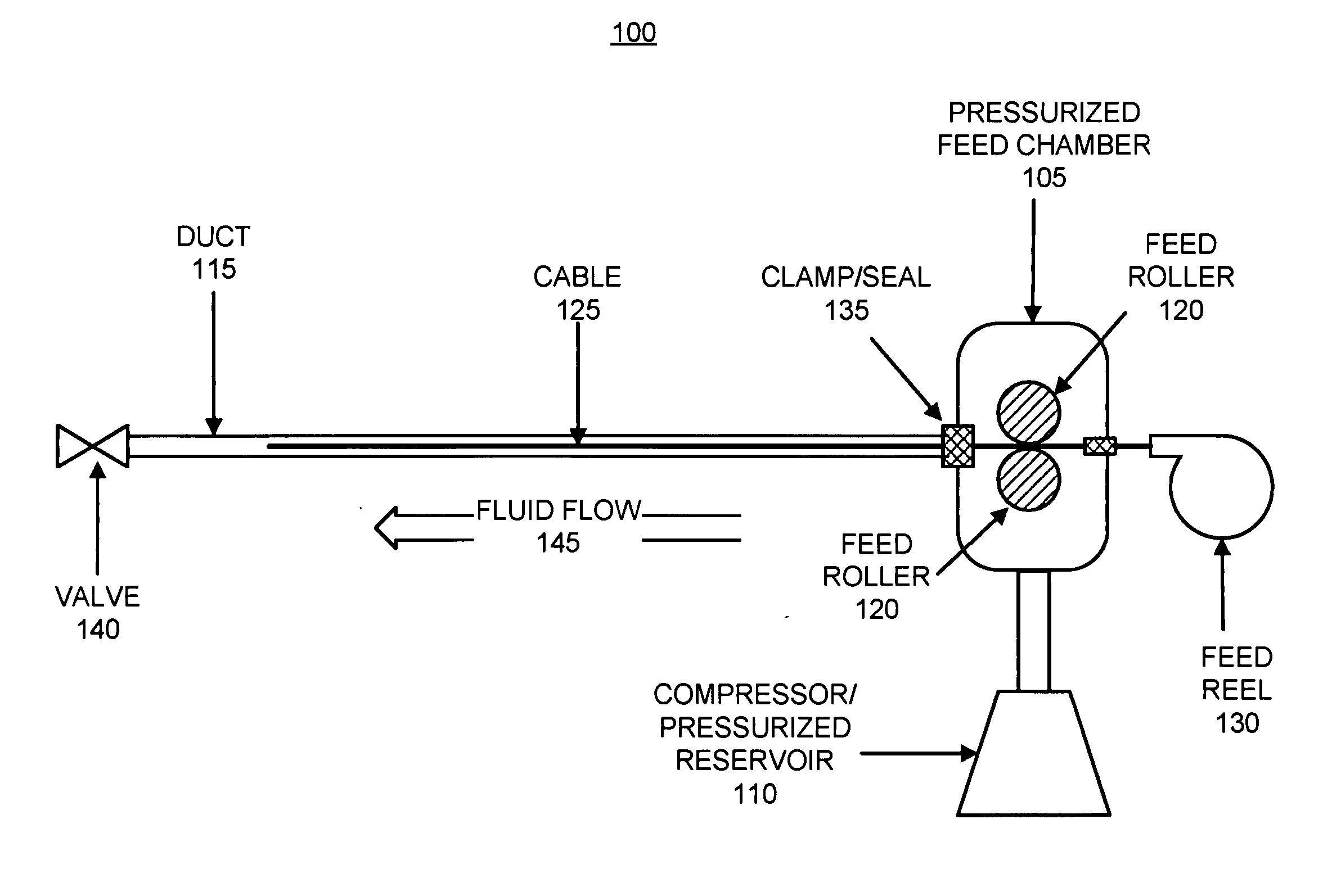
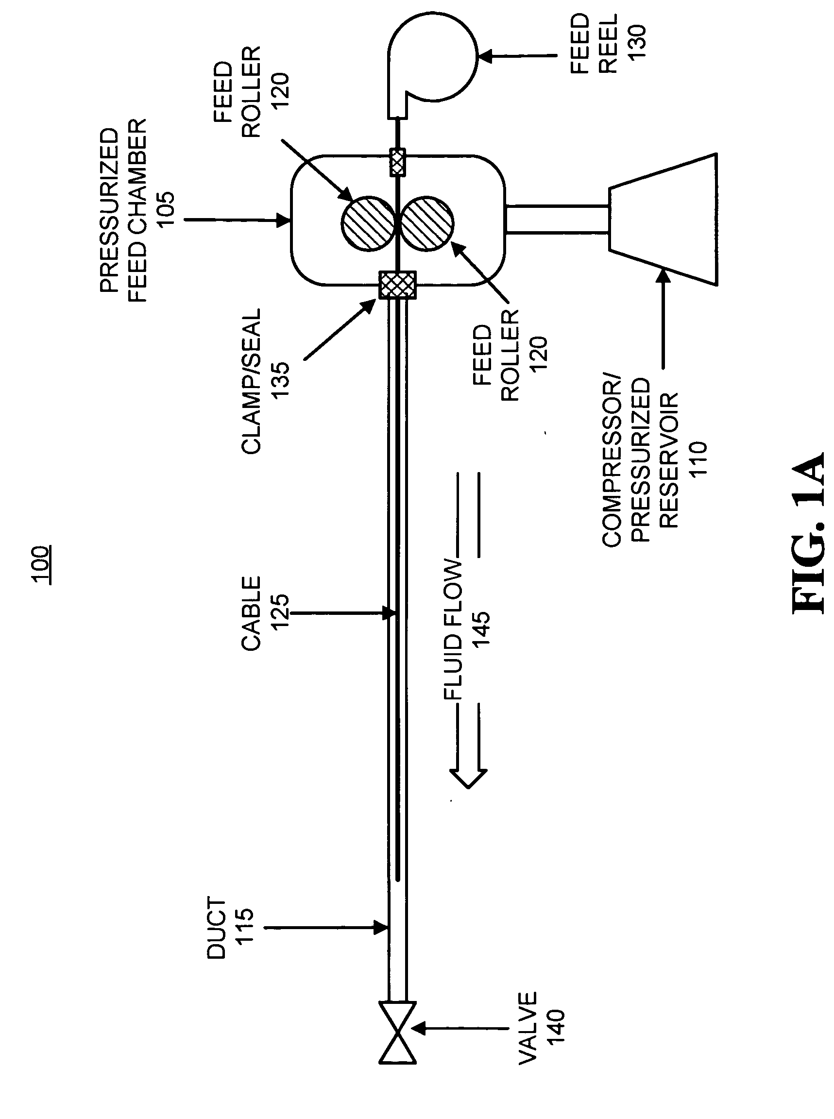
[0005] In accordance with another aspect consistent with the principles of the present invention, an apparatus for facilitating the placement of a cable inside of a duct comprises a valve configured to be coupled to an end of the duct and to control flow of a pressurized fluid outward from the inside of the duct. The valve is designed to automatically open and close in response to sensing pressure inside of the duct. Alternatively, the valve may be actuated by a timer or upon command from an external element.

Problems solved by technology

Existing cable blowing techniques, however, are difficult to apply over distances spanning more than a few kilometers.
The flow of a fluid through an extremely long and narrow duct becomes greatly impeded due primarily to viscous flow characteristics, resulting in a high back-pressure experienced at the originating end of the duct.
This problem can limit the distances over which existing cable blowing techniques are applied, and can impose constraints on the types of ducts that can be used, as well as the types of cables that may be deployed within a given duct.
Additionally, existing cable blowing techniques require that relatively high pressures be applied to the end of a duct through which a cable is being fed.
These high pressures can result in duct “blow-outs,” where the high pressure causes ruptures in the walls of the duct, or sealing / clamping failures, where the seal between the duct and the unit applying pressurized fluid to the duct ruptures or fails.

Method used


Image

  • Systems and methods for controlling duct pressurization for cable installation
  • Systems and methods for controlling duct pressurization for cable installation
  • Systems and methods for controlling duct pressurization for cable installation

Examples


Embodiment Construction

[0015] The following detailed description of the invention refers to the accompanying drawings. The same reference numbers in different drawings may identify the same or similar elements. Also, the following detailed description does not limit the invention. Instead, the scope of the invention is defined by the appended claims and their equivalents.

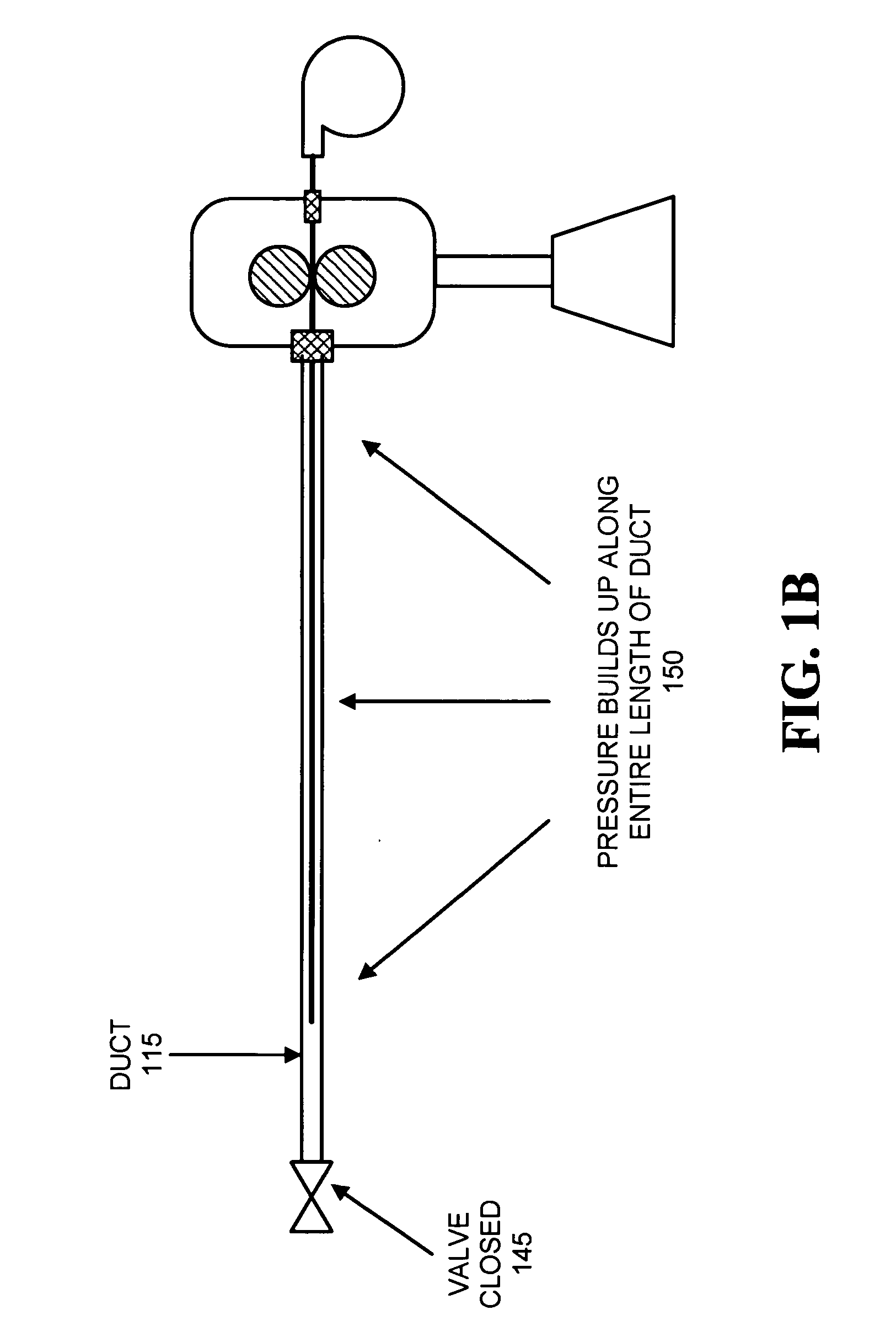
[0016] Systems and methods consistent with principles of the invention involve inserting a cable into a proximal end of a duct and applying pressurized fluid, such as compressed air, to the duct to carry the cable through the length of the duct. In particular, systems and methods consistent with principles of the invention further involve temporarily closing the distal end of the duct to allow pressure to build within the duct and then opening the duct to trigger an efflux of pressurized fluid which propels the cable through the duct. Use of a valve or the like at the distal end to permit uniform pressurization inside the duct may enable...


PUM


Abstract

A system includes a duct, a pressurized fluid source, and a valve. The duct receives one or more cables and the pressurized fluid source couples to a first end of the duct and produces fluid pressure within the duct. The valve couples to a second end of the duct and is closed for a time to build pressure within the duct, and then opened to permit the fluid under pressure within the duct to escape rapidly from the duct and propel the one or more cables through the duct.

Description

FIELD OF THE INVENTION [0001] The present invention relates generally to utility cable placement techniques and, more particularly, to utility cable placement within ducts using fluid pressurization. BACKGROUND OF THE INVENTION [0002] In the field of utility cable installation, there are existing techniques for using the viscous flow of a fluid, such as air, through ducts to install utility cables within the ducts. Such cable “blowing” techniques have been applied to the installation of utility cables in building risers, over relatively short distances along the ground, or in suspended cables. [0003] Existing cable blowing techniques, however, are difficult to apply over distances spanning more than a few kilometers. The flow of a fluid through an extremely long and narrow duct becomes greatly impeded due primarily to viscous flow characteristics, resulting in a high back-pressure experienced at the originating end of the duct. This problem can limit the distances over which existin...

Claims


Application Information

Patent Timeline
Patent Type & Authority Applications(United States)
IPC IPC(8): E21C29/16
CPCH02G1/086G02B6/4464G02B6/52
Inventor FEE, JOHN A.MCKIEL, FRANK A. JR.
Owner VERIZON PATENT & LICENSING INC
Learn More