Attaching structure of resolver, dynamo-electric machine and attaching method of resolver

a technology of dynamo-electric machines and resolvers, which is applied in the direction of dynamo-electric components, mechanical energy handling, generators/motors, etc., can solve the problems of reducing detection accuracy and inability to accurately detect the rotational position of shafts, and achieve the effect of preventing the lowering of assembly position accuracy

Inactive Publication Date: 2006-10-05
SHOWA CORP
View PDF14 Cites 19 Cited by
  • Summary
  • Abstract
  • Description
  • Claims
  • Application Information

AI Technical Summary

Benefits of technology

[0008] One or more embodiments of the present invention provide an attaching structure of a resolver which can prevent an accuracy of assembling position from being lowered with respect to a resolver rotor portion of a resolver stator portion, a dynamo-electric machine, and an attaching method of the resolver.

Problems solved by technology

Accordingly, there is a problem that a rotational position of the shaft cannot be accurately detected.
In particular, in the case that both side end surfaces of the resolver stator portion are pinched by the vertical surface portion of the concave portion of the resolver stator portion side attaching portion and the cover member so as to be positioned and firmly fixed, a magnetic strain caused by a great fastening force is generated in the resolver stator core by a fastening member of the cover member, so that there is a problem that an accuracy of detection is diminished.

Method used


Image

  • Attaching structure of resolver, dynamo-electric machine and attaching method of resolver
  • Attaching structure of resolver, dynamo-electric machine and attaching method of resolver
  • Attaching structure of resolver, dynamo-electric machine and attaching method of resolver

Examples


Embodiment Construction

[0020] Next, a description will be given of a dynamo-electric machine in accordance with embodiments of the present invention with reference to the accompanying drawings.

[0021] The following description will be given exemplifying a DC brushless motor as the dynamo-electric machine, however, the present invention is not limited to the DC brushless motor. Instead, the present invention can be employed in various dynamo-electric machines, for example, direct-current type and alternating-current type step motors and the like.

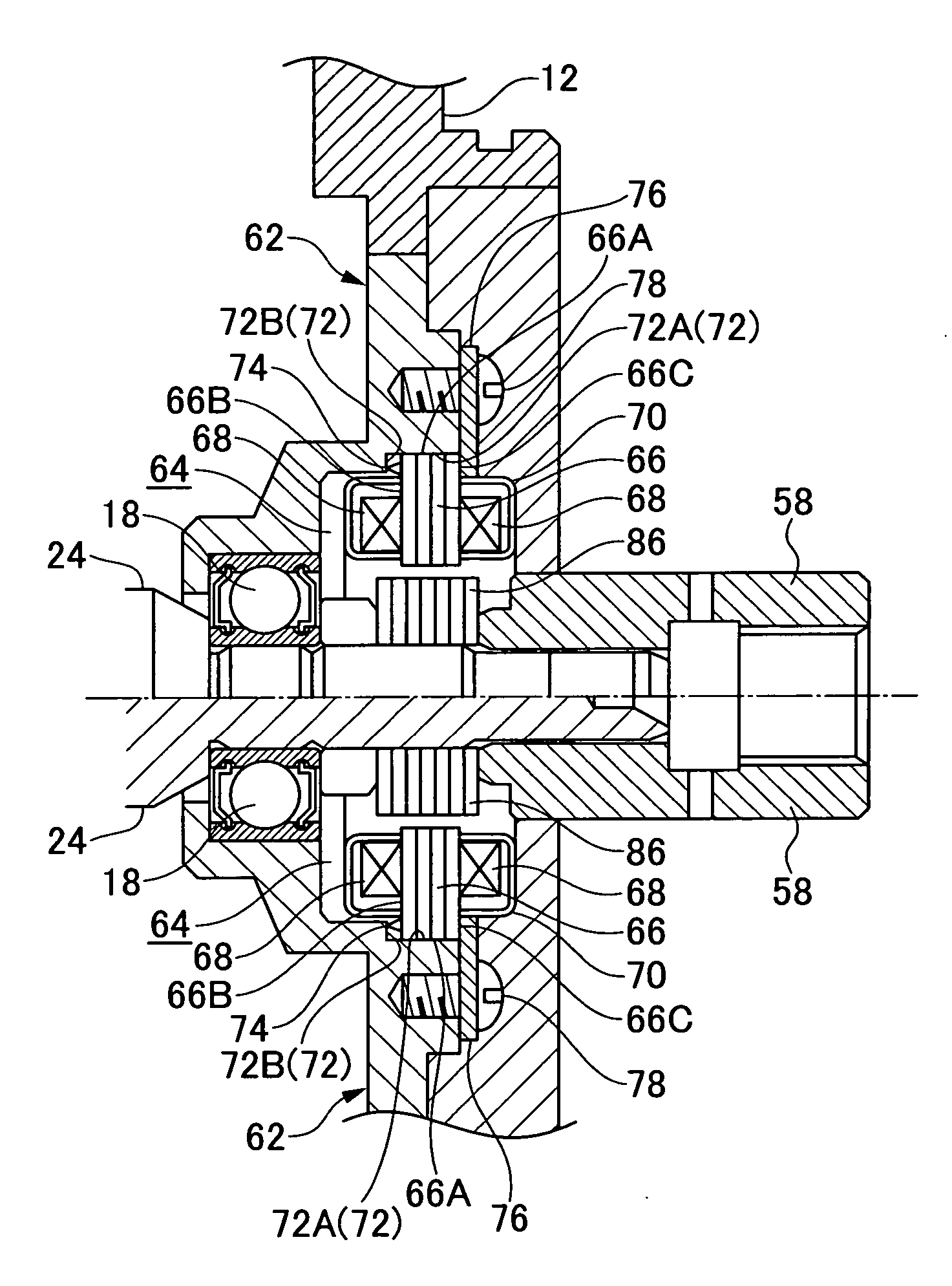
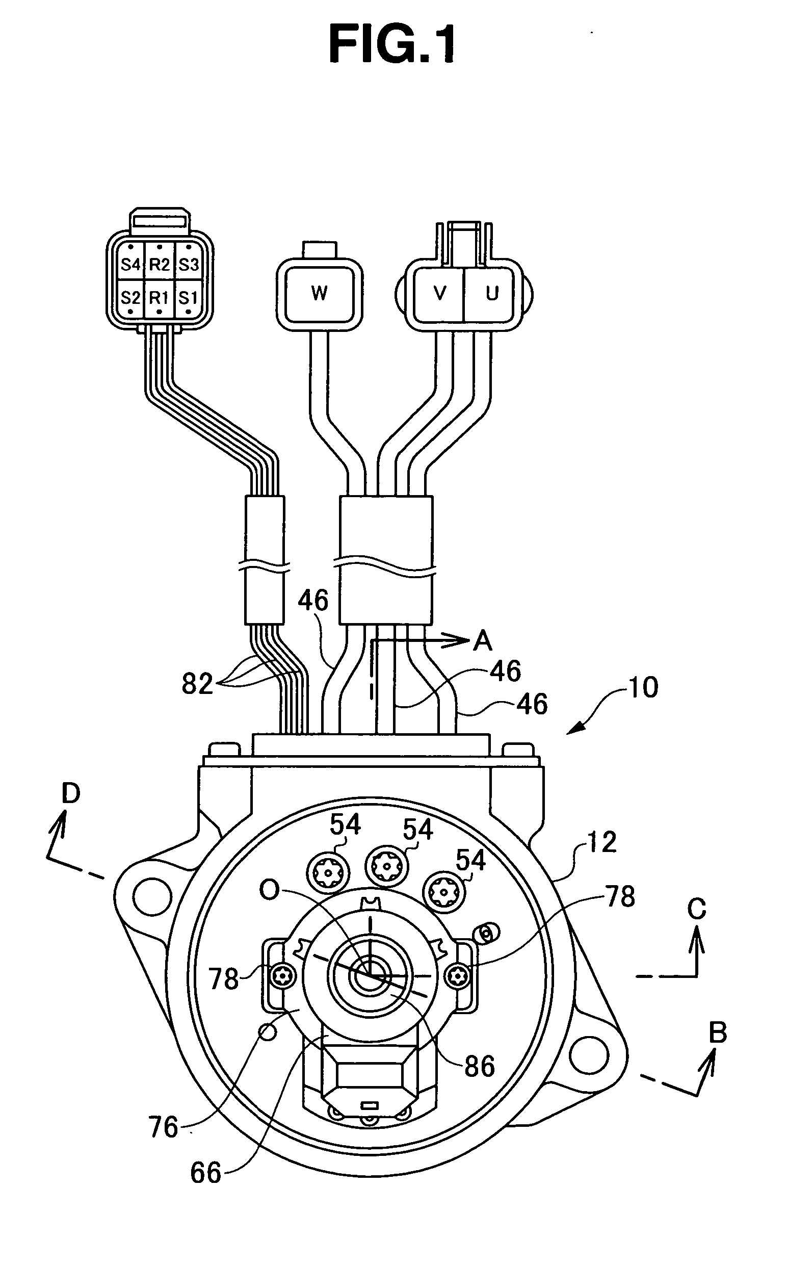
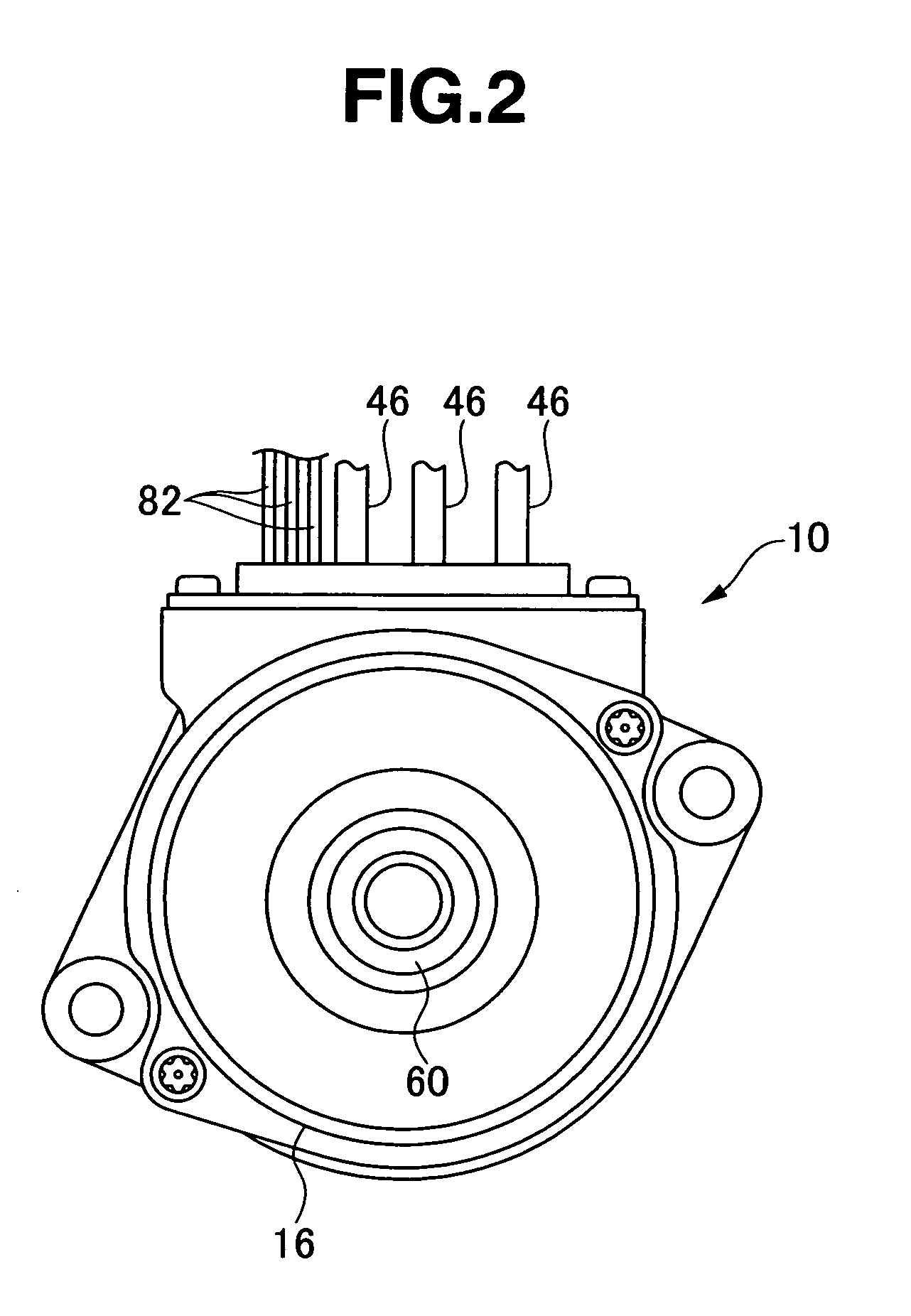
[0022] As shown in FIGS. 1 to 3, a motor 10 is structured by fitting a frame 16 in which a cylindrical stator 14 is received to a housing 12 made of an aluminum material or the like. A first bearing 18 is provided in the housing 12, a second bearing 20 is provided in the frame 16, and a shaft 24 of a rotor 22 is held by the first bearing 18 and the second bearing 20, whereby the rotor 22 can be rotated.

[0023] Further, the stator 14 is formed by laminating a silic...


PUM


Abstract

A resolver stator portion is attached to a resolver stator portion side attaching portion formed at a position facing to a resolver rotor portion via an elastic ring. Thus, it is possible to absorb a dimensional error of the resolver stator portion side attaching portion on the basis of an elastic deformation of the elastic ring even in the case that the dimensional error is generated in the resolver stator portion side attaching portion.

Description

BACKGROUND OF THE INVENTION [0001] 1. Field of the Invention [0002] The present invention relates to an attaching structure of a variable reluctance (VR) type resolver detecting a rotational position of a rotor, and a dynamo-electric machine provided with the attaching structure of the resolver, and an attaching method of the resolver. [0003] 2. Description of the Related Art [0004] As shown in FIG. 7, a conventional DC brushless motor 100 is provided with a resolver rotor portion 104 attached to a shaft 102, a resolver stator portion 106 arranged in an outer side in a diametrical direction of the resolver rotor portion 104, and a coil portion 108 positioned in both sides in an axial direction of the resolver stator portion 106. A rotational position of the shaft 102 is detected by the resolver rotor portion 104 and the resolver stator portion 106. [0005] In this case, the resolver stator portion 106 and the coil portion 108 are received in a case member 110. The case member 110 is ...

Claims


Application Information

Patent Timeline
Patent Type & Authority Applications(United States)
IPC IPC(8): H02K7/09
CPCH02K11/225
Inventor TAKEKAWA, JUNYA
Owner SHOWA CORP
Why Eureka
Try Eureka