Electronic circuitry protected against transient disturbances and method for simulating disturbances

Active Publication Date: 2006-10-05
IROC TECH
View PDF8 Cites 65 Cited by
  • Summary
  • Abstract
  • Description
  • Claims
  • Application Information

AI Technical Summary

Benefits of technology

[0014] It is one object of the invention to improve protection of logic circuitry against transient

Problems solved by technology

Electronic circuits are subjected to various types of disturbances due either to their ageing or to external disturbances.
It is therefore not sufficient to provide protection against permanent faults, but it has become necessary to protect against transient disturbances as well.
Moreover, it is not sufficient to protect against transient disturbances affecting only the latches, but also against those affecting the combinatory logic circuits.
Consequently, known protection systems, consisting in using hardened cells for fabrication of the latche

Method used


Image

  • Electronic circuitry protected against transient disturbances and method for simulating disturbances
  • Electronic circuitry protected against transient disturbances and method for simulating disturbances
  • Electronic circuitry protected against transient disturbances and method for simulating disturbances

Examples


Embodiment Construction

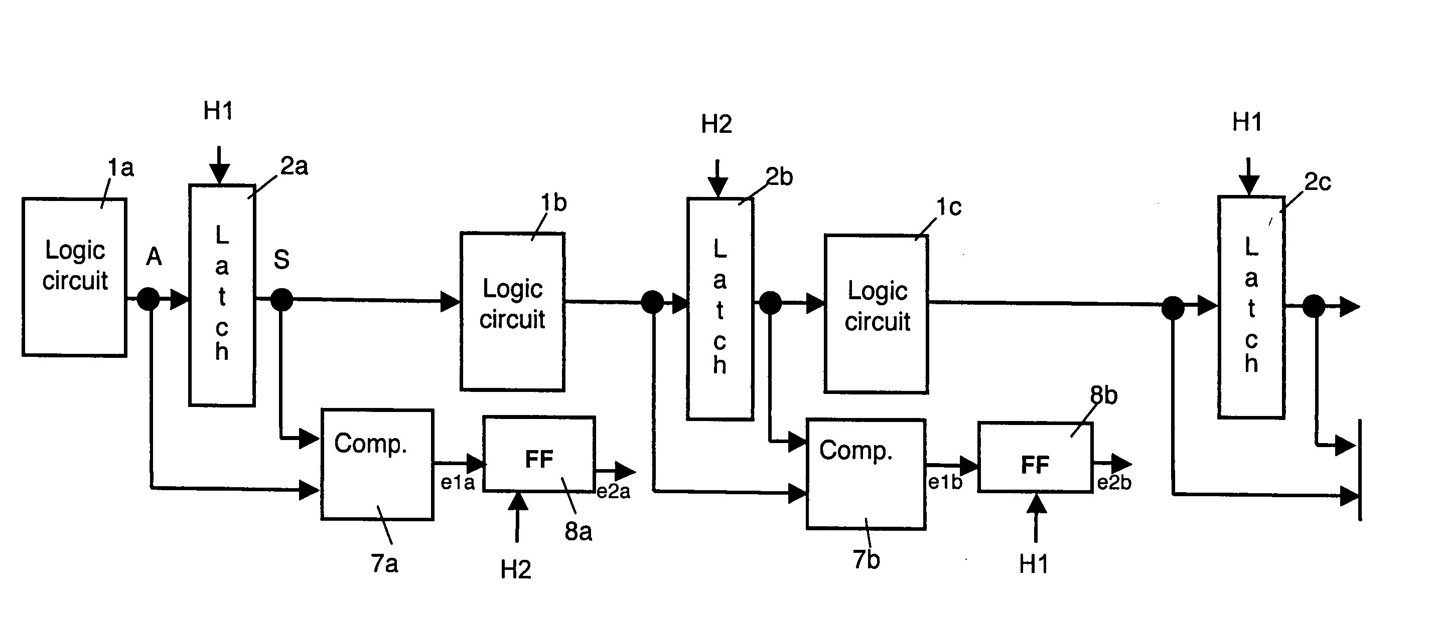
[0030] The invention applies to electronic circuitry comprising, as represented in FIG. 4, a plurality of successive stages, alternatively odd and even stages. Each stage comprises at least one combinatory logic circuit 1 (1a for the first stage, 1b for the second stage, 1c for the third stage, etc . . . ) having at least one output connected to the input of an associated first latch 2 (2a for the first stage, 2b for the second stage, 2c for the third stage, etc . . . ).

[0031] In the description below, for the sake of clarity, each logic circuit has been represented with a single input, the different stages being connected strictly in series. In practice, each logic circuit can comprise several inputs and the output of a stage can, in addition, be looped back onto one of the inputs of the logic circuit of a previous stage.

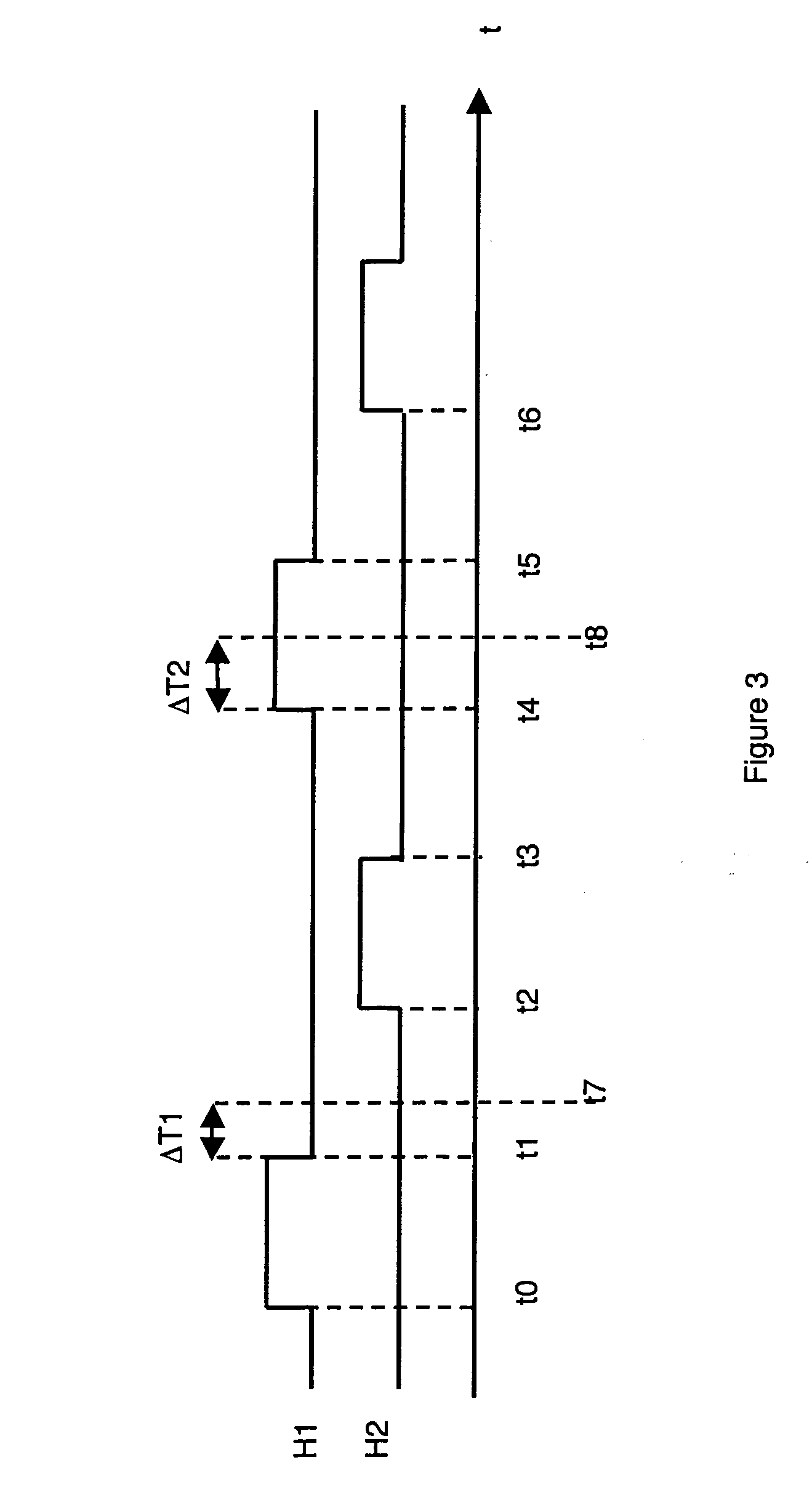
[0032] As represented in FIGS. 3 and 4, first and second clock signals H1, H2 are respectively applied to a clock input of the first latches (2a, 2c) of the odd ...


PUM


Abstract

The circuitry comprises successive stages, each comprising a combinatory logic circuit connected to the input of a first latch. Staggered clock signals are respectively associated with the first latches of the odd and even stages. Means for detecting a transient disturbance affecting the first latch of a stage and liable to propagate downstream, compare, in each stage, a value present on the output of the first latch of the stage considered at an observation time with a value present on the input of said first latch at a predetermined observation time taking account of the various propagation times.

Description

BACKGROUND OF THE INVENTION [0001] The invention relates to electronic circuitry comprising a plurality of successive stages, alternately odd and even stages, each stage comprising at least one combinatory logic circuit having at least one output connected to the input of an associated first latch, a clock signal being applied to a clock input of each first latch, the clock signal successively taking, during a clock cycle, a high level between a rising front and a descending front, and a low level from said descending front until the rising front of the next clock cycle, each first latch being transparent during the high level of the corresponding clock signal. [0002] It also relates to a method for simulating disturbances. STATE OF THE ART [0003] Electronic circuits are subjected to various types of disturbances due either to their ageing or to external disturbances. These external disturbances, which can in particular be due to particle bombardments, in particular ionizing particl...

Claims


Application Information

Patent Timeline
IPC IPC(8): H03K3/00
CPCG01R31/318536H03K3/0375H03K3/013
Inventor NICOLAIDIS, MICHEL
Owner IROC TECH
Why Eureka
Try Eureka