
Ambient light sensing solar powered pulsed LED visual indicator apparatus and method

Inactive Publication Date: 2006-10-05
EDWARDS SYST TECH
View PDF6 Cites 30 Cited by
  • Summary
  • Abstract
  • Description
  • Claims
  • Application Information

AI Technical Summary

Benefits of technology

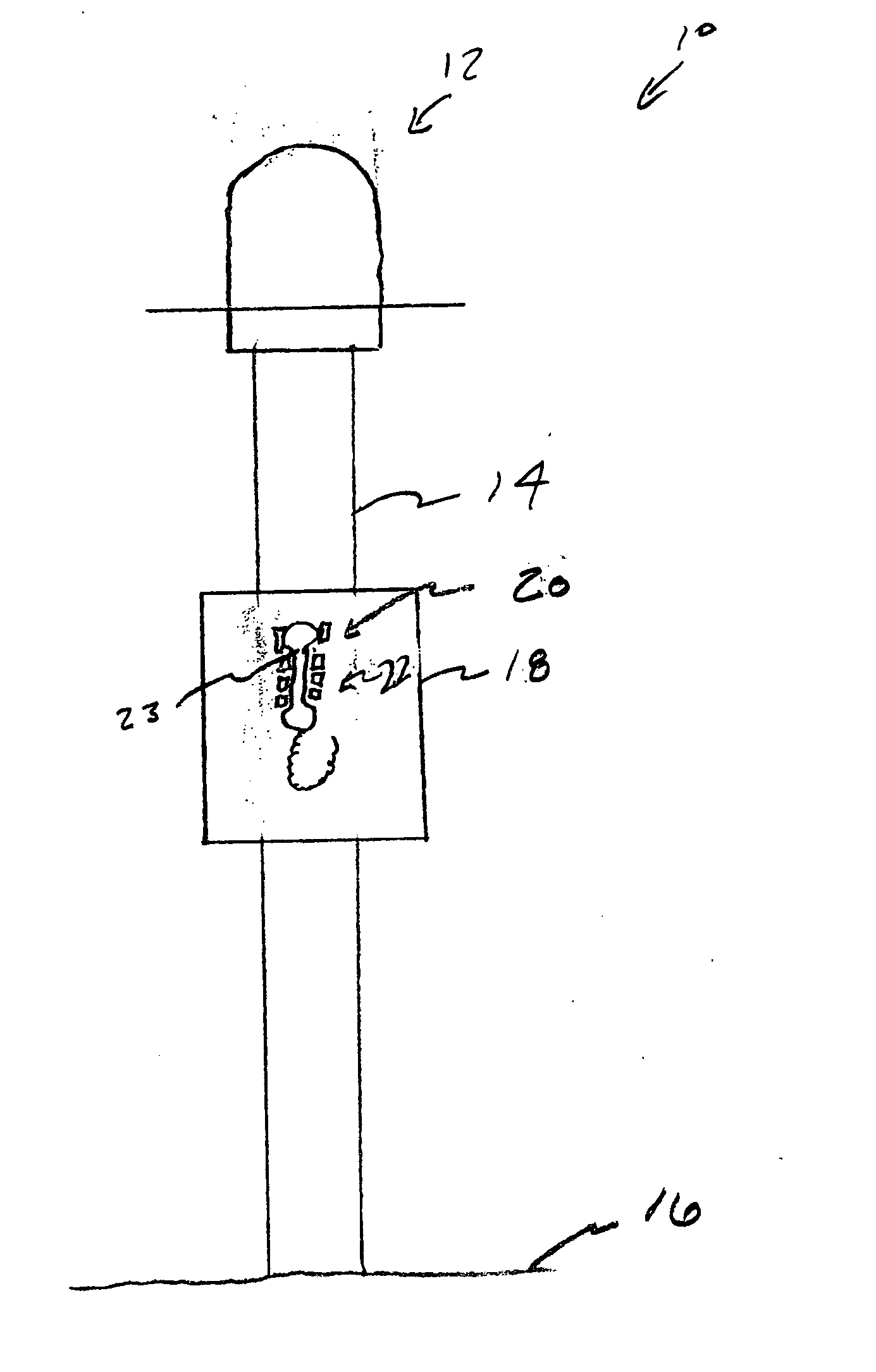
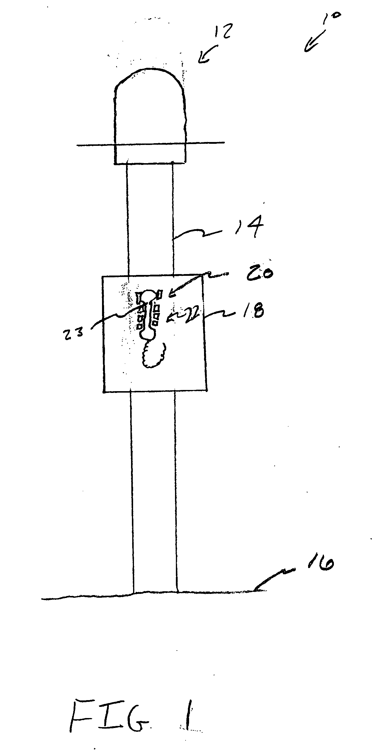
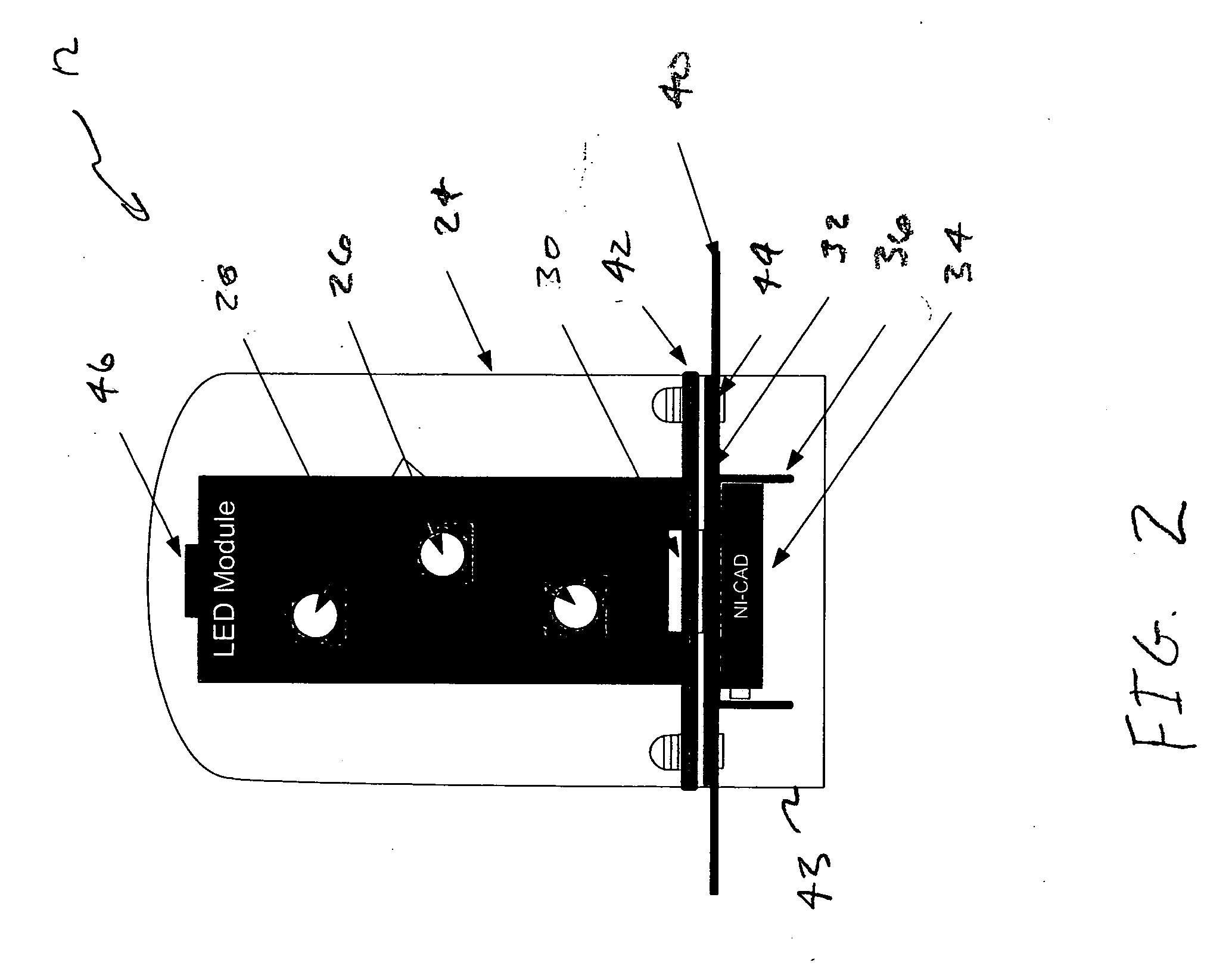
[0007] In accordance with one embodiment of the present invention, a visual indicator is provided. The visual indicator includes a solar panel, a rechargeable battery operatively connected to the solar panel for charging the rechargeable battery with power from the solar panel, a light emitting diode (LED) operatively connected to the rechargeable battery to emit light, and a controller operatively connected to the rechargeable battery and the LED to control operating characteristics of the LED.
[0008] In accordance with

Problems solved by technology

Because emergency callboxes may not be located near power lines or other power sources providing power to the visual, light-emitting indicator can be problematic.

Method used


Image

  • Ambient light sensing solar powered pulsed LED visual indicator apparatus and method
  • Ambient light sensing solar powered pulsed LED visual indicator apparatus and method
  • Ambient light sensing solar powered pulsed LED visual indicator apparatus and method

Examples


Embodiment Construction

[0017] The invention will now be described with reference to the drawing figures, in which like reference numerals refer to like parts throughout. An embodiment in accordance with the present invention provides a solar-powered, light-emitting visual indicator. The solar-powered, light-emitting visual indicator includes a rechargeable battery for providing power to the indicator during periods of darkness.

[0018] In some embodiments of the invention, an actuator is provided such as an actuator like a telephone associated with a callbox, along with the visual indicator for when an emergency situation arises. The visual indicator will transform from a steady light-emitting state to a strobe or flashing light emission when the actuator has been actuated. In some embodiments of the invention, the light-emitting visual indicator is associated with a telephone for providing communication between the person signaling the emergency and a system monitoring the callbox or emergency services. I...


PUM


Abstract

A visual indicator includes a solar panel, a rechargeable battery operatively connected to the solar panel for charging the rechargeable battery with power from the solar panel, a light emitting diode (LED) operatively connected to the rechargeable battery to emit light, and a controller operatively connected to the rechargeable battery and the LED to control operating characteristics of the LED. A method of operating a visual sensor includes recharging a battery from a solar panel, emitting light with a light emitting diode (LED) from power provided by the battery, sensing ambient light conditions proximate to the visual sensor, varying an intensity of light emitted from the LED based on the sensed ambient light conditions.

Description

FIELD OF THE INVENTION [0001] The present invention relates generally to signaling devices. More particularly, the present invention relates to a solar-powered, light-emitting signaling device. BACKGROUND OF THE INVENTION [0002] Visual indicators, such as lights, have long been used for calling attention to particular items. For example, exit doors and emergency callboxes, such as those located along highways, for assisting stranded motorists, or found on college campuses, or in other areas which have often been lit by light-emitting visual indicator devices. Often the light-emitting device is in a constantly on position displaying a steady light which may be, for example, blue, red, yellow, green or any desired color to indicate the location of an emergency callbox. [0003] Light-emitting devices require power in order to emit a steady stream of light. Because emergency callboxes may not be located near power lines or other power sources providing power to the visual, light-emitting...

Claims


Application Information

Patent Timeline
IPC IPC(8): G08B5/00
CPCG08B5/36
Inventor ARCARIA, ANGELO S.LEBLANC, RAYMONDTAYLOR, KENNETH R.
Owner EDWARDS SYST TECH
Learn More