
Congestion control network relay device and method

a network relay and congestion control technology, applied in data switching networks, frequency-division multiplexes, instruments, etc., can solve the problems of unavoidable high-priority packet congestion, difficult to carry on effective communication, and liable to occur congestion

Inactive Publication Date: 2006-10-05
FUJITSU LTD
View PDF3 Cites 76 Cited by
  • Summary
  • Abstract
  • Description
  • Claims
  • Application Information

AI Technical Summary

Benefits of technology

[0028] The present invention was created in view of the above circumstances, and an object thereof is to provide congestion control network relay device and method which can prevent redundant retransmission of packets already delivered to a receiving-side device.

Problems solved by technology

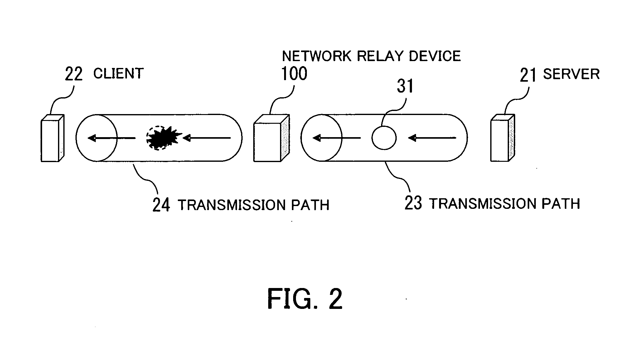
In cases where wideband and narrowband transmission paths coexist, congestion is liable to occur when data which has been transmitted via a wideband transmission path passes through a narrowband transmission path.
Congestion indicates a situation where increased network traffic makes it difficult to carry on effective communication.
However, if high-priority packets are transmitted in excess of the bandwidth allocated thereto, congestion of high-priority packets is still unavoidable.
However, if packets are discarded continuously until the congestion is resolved, as mentioned in Unexamined Japanese Patent Publications No.
H02-90751 and No. 2003-23443, extra packets are generated by, for example, a process of retransmitting all discarded packets from the first one that failed to be received, which hinders effective use of resources such as network paths.
As a result, the congestion may possibly become even worse or the quality of communication lowers.
This problem also arises in cases where the bandwidth control is performed according to priority levels.
Specifically, FIG. 24 shows a situation where duplicate retransmission packets have been generated as a result of congestion, eventually making it impossible to effectively use the bandwidth secured by the bandwidth control.
Even in the case where a bandwidth is secured for priority packets by the bandwidth control, congestion occurs if priority packets arrive in excess of the secured bandwidth, with the result that part of the priority packets are discarded.
In the case of severer congestion, however, the beneficial function of SACK does not work effectively; on the contrary, the TCP congestion avoidance action is delayed by SACK, with the result that unnecessary retransmission packets are transmitted.
However, SACK permits only a maximum of four pieces of information to be carried by one packet, and accordingly, if packets are frequently lost at random due to congestion, it is not possible to add information indicative of all of the randomly received packets to an acknowledgment packet.
Thus, in the situation where data packets are frequently lost, not only retransmission of lost packets but redundant retransmission of already delivered packets occur despite the use of SACK.

Method used


Image

  • Congestion control network relay device and method
  • Congestion control network relay device and method
  • Congestion control network relay device and method

Examples


Embodiment Construction

[0057] Preferred embodiments of the present invention will be described below with reference to the accompanying drawings.

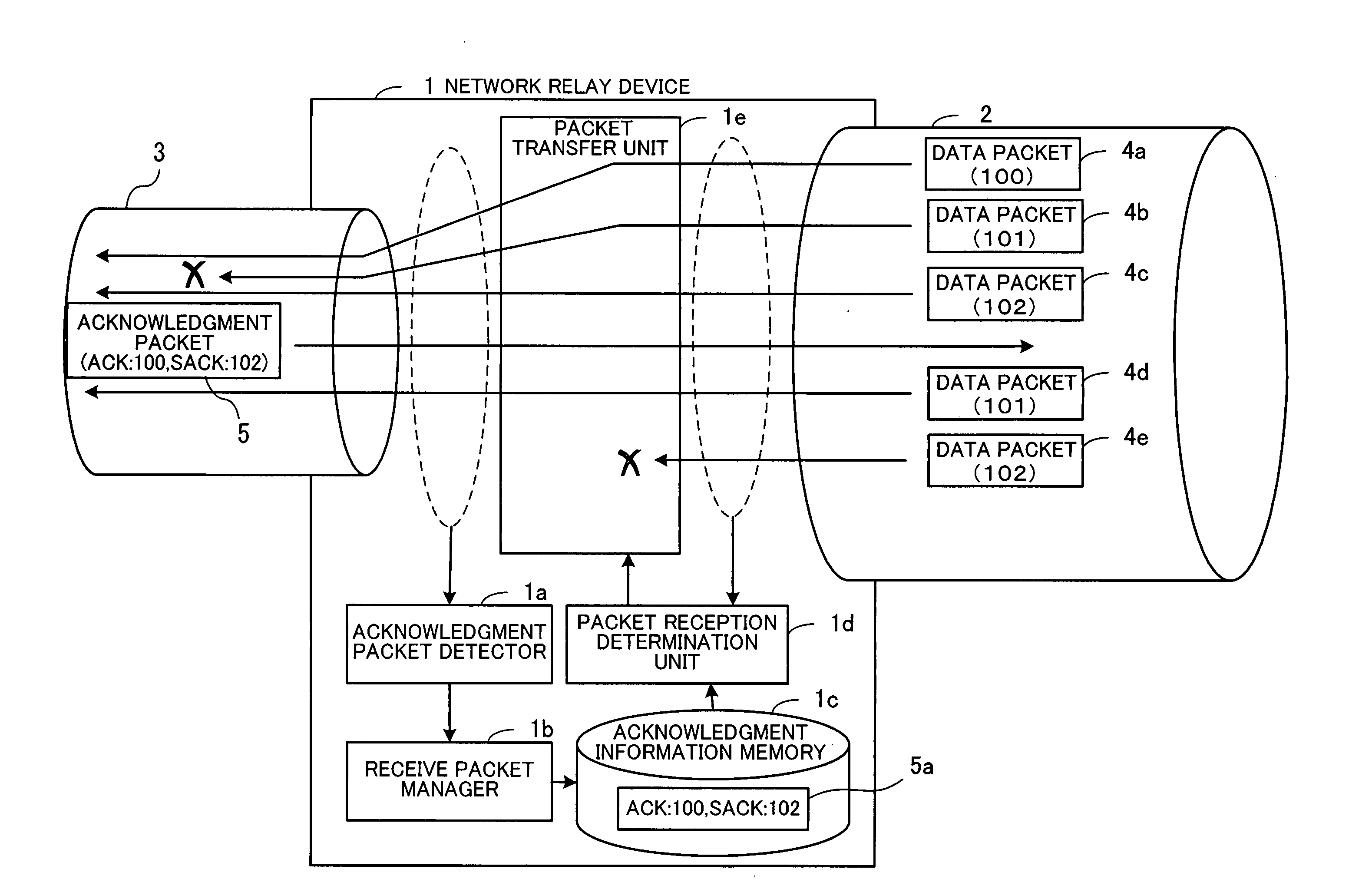
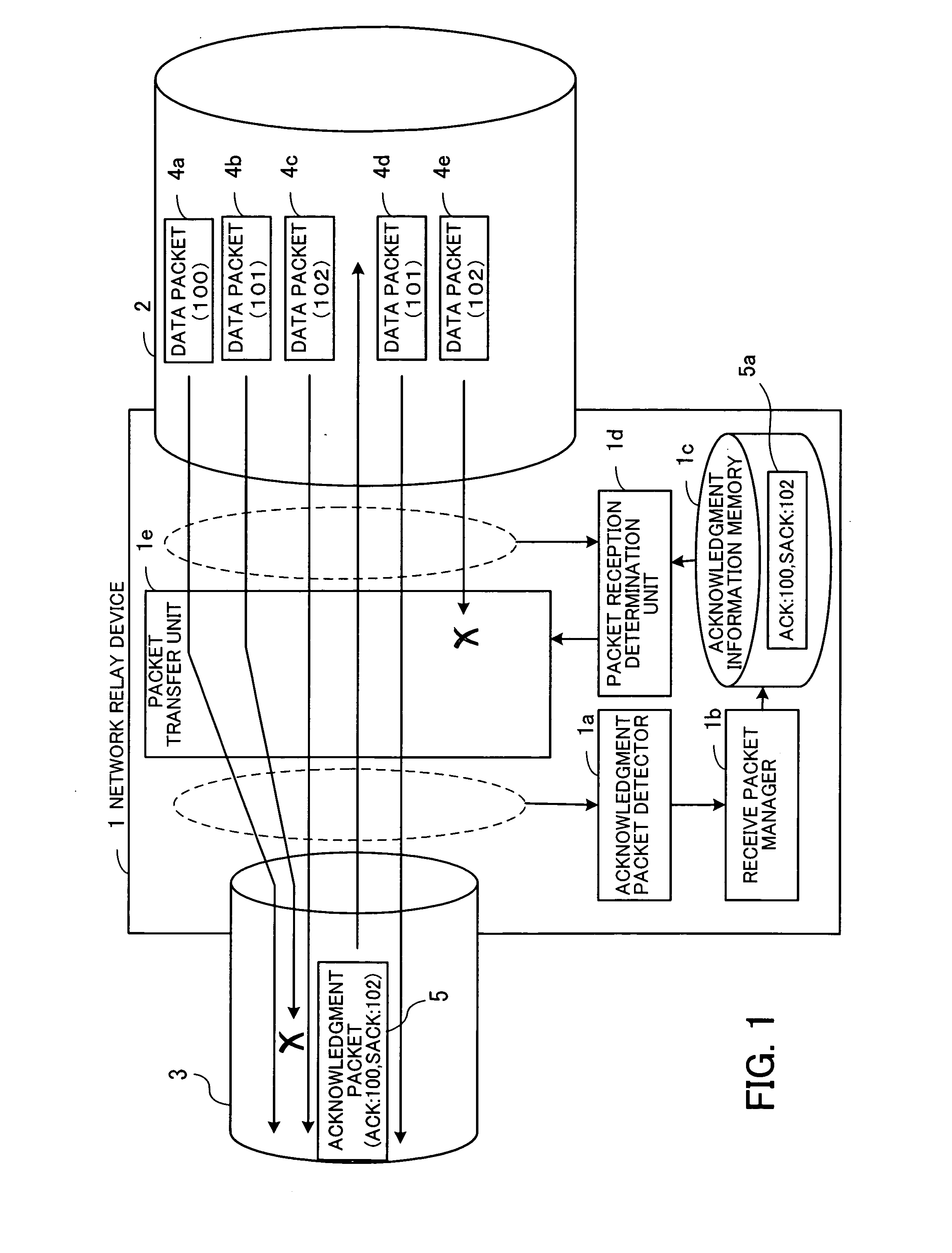
[0058]FIG. 1 schematically illustrates an embodiment of the present invention. A congestion control network relay device 1 is adapted to relay data between transmission paths 2 and 3. In the example shown in FIG. 1, it is assumed that the transmission speed of the transmission path 3 is lower than that of the transmission path 2, and also that the network relay device 1 is connected to a transmitting-side device via the transmission path 2, as well as to a receiving-side device via the transmission path 3. The congestion control network relay device 1 comprises an acknowledgment packet detector 1a, a receive packet manager 1b, an acknowledgment information memory 1c, a packet reception determination unit 1d, and a packet transfer unit 1e.

[0059] The acknowledgment packet detector 1a detects, from among packets transferred through the transmission paths 2 and 3, ...


PUM


Abstract

A congestion control network relay device capable of preventing redundant retransmission of packets which are already delivered to a receiving-side device. When an acknowledgment packet is detected by an acknowledgment packet detector, a receive packet manager stores acknowledgment information in an acknowledgment information memory. If first and second data packets are retransmitted thereafter from a transmitting-side device and input to the congestion control network relay device, a packet reception determination unit judges, for example, that the first data packet has not yet been received by the receiving-side device while the second data packet has already been received by the receiving-side device. In this case, a packet transfer unit transfers the first data packet to the receiving-side device and discards the second data packet.

Description

CROSS-REFERENCE TO RELATED APPLICATIONS [0001] This application is based upon and claims the benefits of priority from the prior Japanese Patent Application No. 2005-101162, filed on Mar. 31, 2005, the entire contents of which are incorporated herein by reference. BACKGROUND OF THE INVENTION [0002] 1. Field of the Invention [0003] The present invention relates to congestion control network relay devices and methods for controlling network congestion, and more particularly, to congestion control network relay device and method for controlling retransmission of data at the time of congestion. [0004] 2. Description of the Related Art [0005] Large-scale networks often include both wideband transmission paths and narrowband transmission paths. For example, some networks include high-speed transmission paths constituted by optical fibers, as well as low-speed transmission paths dedicated for radio communications. [0006] In cases where wideband and narrowband transmission paths coexist, co...

Claims


Application Information

Patent Timeline
IPC IPC(8): H04J3/22H04L12/26H04L1/00H04J3/16H04L12/801H04L12/911H04L13/08H04L29/08
CPCH04L1/1858H04L1/1874H04L47/10H04L47/12H04L47/32H04L67/2871H04L67/2819H04L67/2828H04L67/28H04L69/14H04L2001/0096H04L67/564H04L67/56H04L67/5651
Inventor OKANO, TETSUYA
Owner FUJITSU LTD
Learn More