
Pumping chamber for a liquefaction handpiece

Inactive Publication Date: 2006-10-05
ALCON INC
View PDF22 Cites 10 Cited by
  • Summary
  • Abstract
  • Description
  • Claims
  • Application Information

AI Technical Summary

Benefits of technology

[0011] The present invention improves upon the prior art by providing a liquefacti

Problems solved by technology

When age or disease causes the lens to become less transparent, vision deteriorates because of the diminished light which can be transmitted to the retina.
Temperature control of the heated solution can be difficult because the fluid tubings feeding the handpiece typically are up to two meters long, and the heated solution can cool considerably as it travels down the length of the tubing.
The pulse repetition rate of this handpiece is less than optimal because of the time required to refill the boiling chamber between pulses.

Method used


Image

  • Pumping chamber for a liquefaction handpiece
  • Pumping chamber for a liquefaction handpiece
  • Pumping chamber for a liquefaction handpiece

Examples


Embodiment Construction

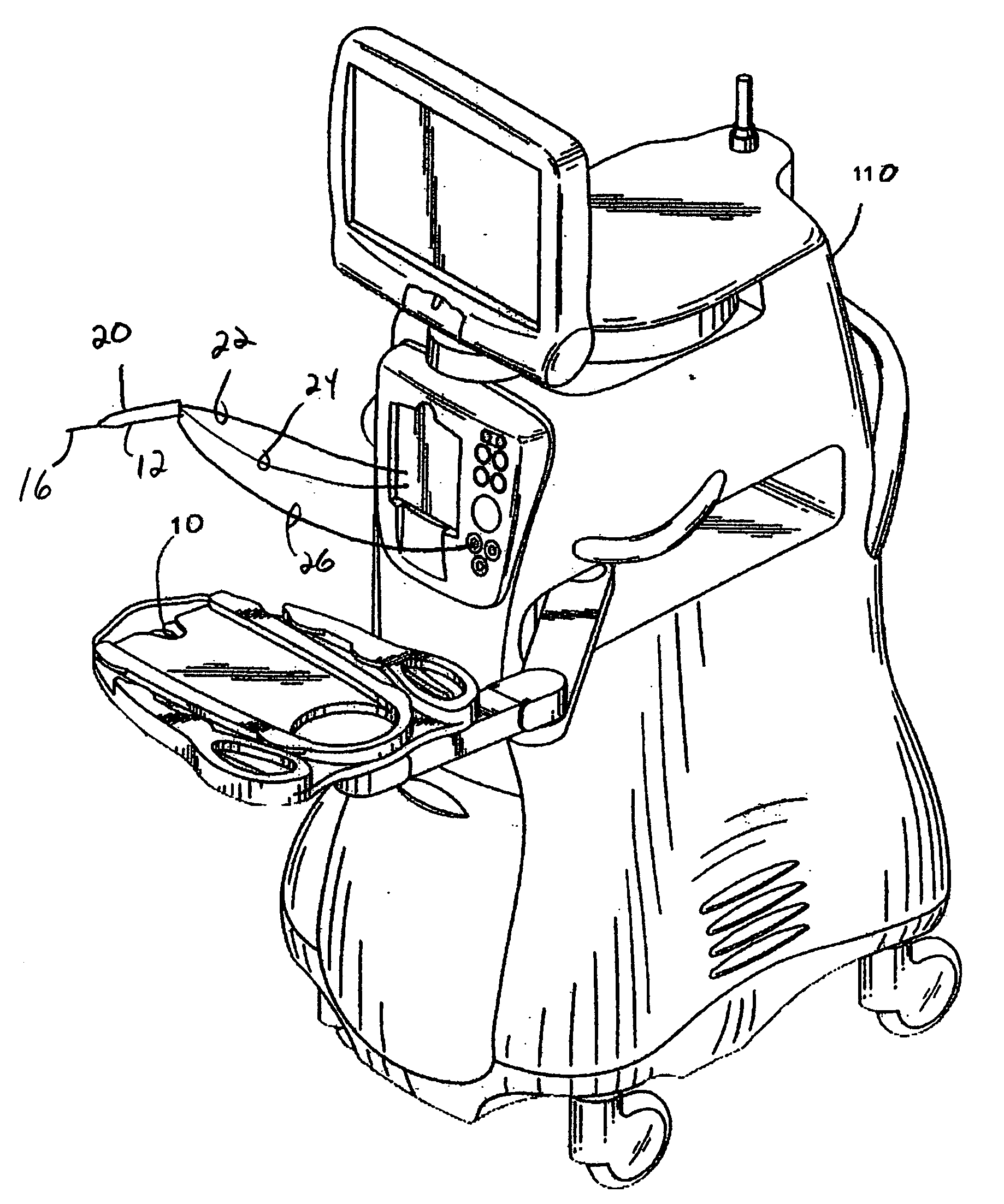
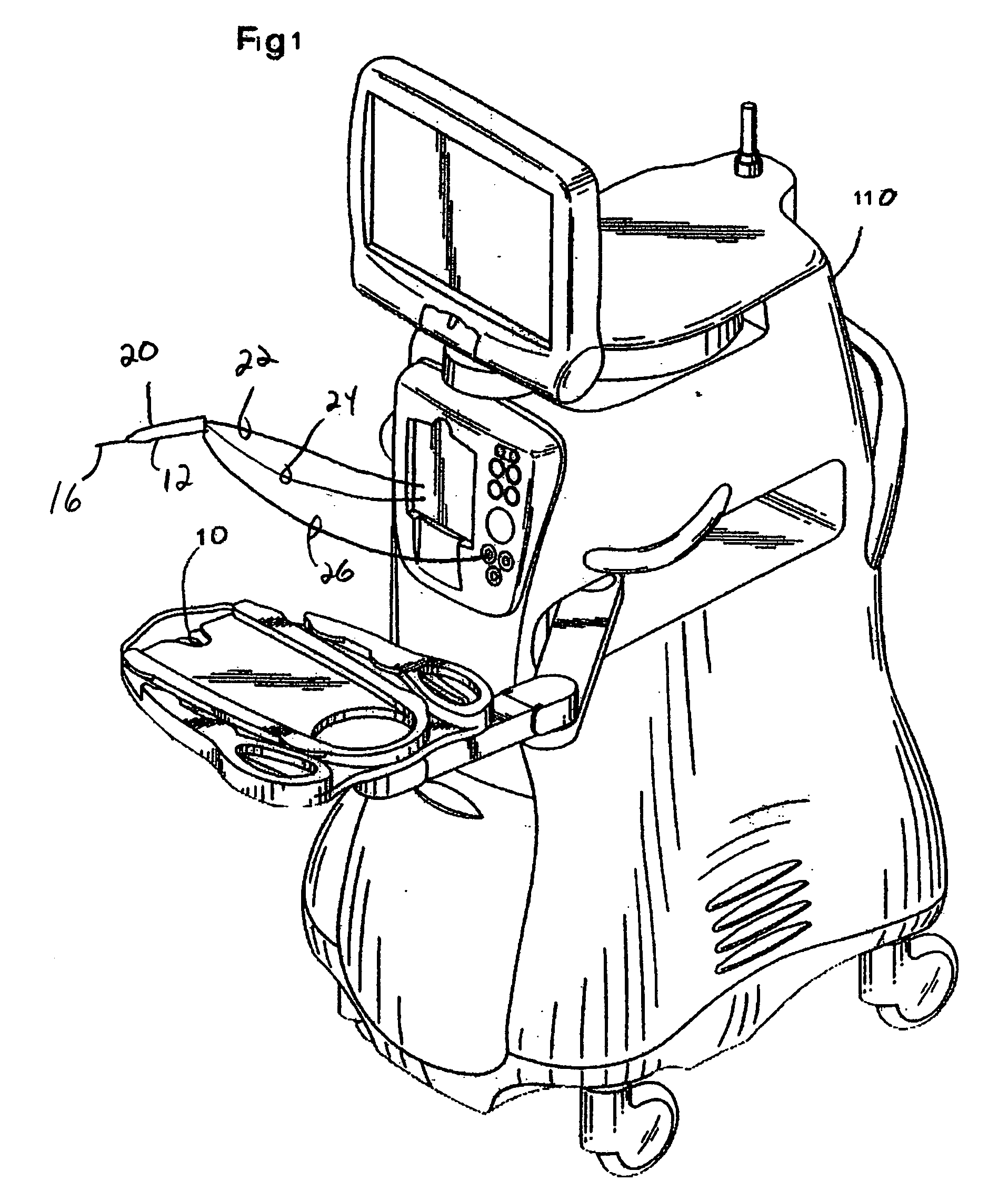
[0018] As best seen in FIG. 1, commercially available surgical systems generally include surgical console 110 having attached mayo tray 10 and handpiece 20 attached to console 110 by aspiration tubing 22, irrigation tubing 24 and power cable 26. Power to handpiece 20 as well as flows of irrigation and aspiration fluids are controlled by console 110, which contains appropriate hardware and software, such as power supplies, pumps, pressure sensors and valves, all of which are well-known in the art.

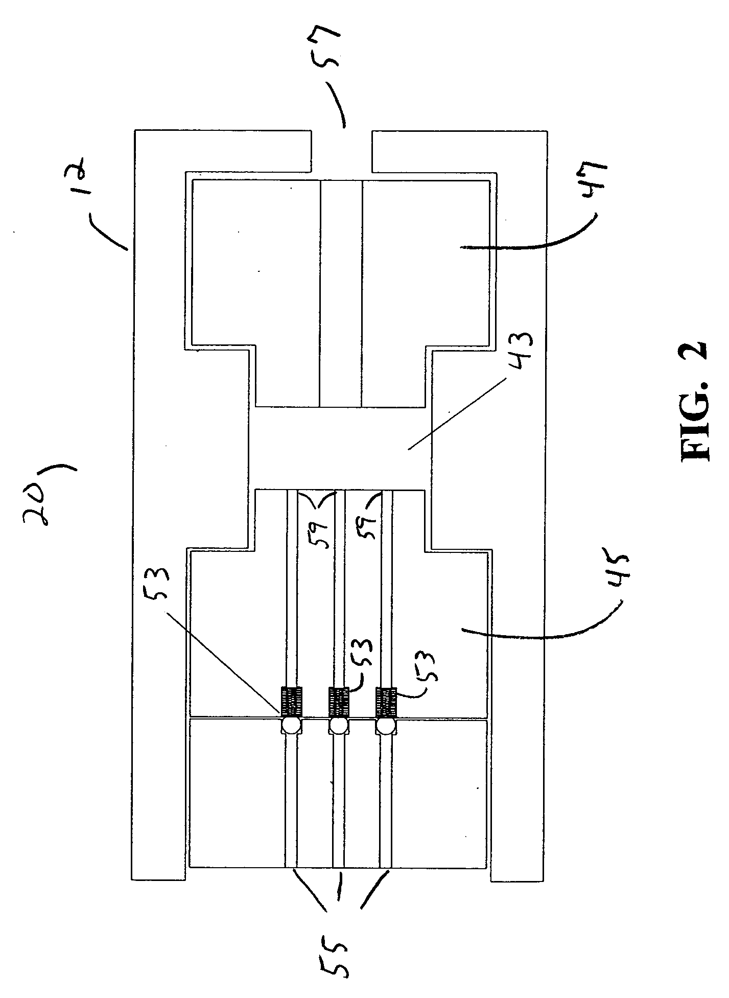
[0019] Handpiece 20 of the present invention generally includes handpiece body 12 and operative tip 16. Contained within body 12, as best seen in FIG. 2, are proximal electrode 45 and distal electrode 47 which define pumping reservoir 43. Electrical power is supplied to electrodes 45 and 47 by insulated wires, not shown. In use, surgical fluid (e.g. saline irrigating solution) enters reservoir 43 through ports 55, check valves 53 and inlets 59, check valves 53 being well-known in the art. E...


PUM


Abstract

A liquefaction surgical handpiece having a plurality of fluid inlets into the boiling chamber.

Description

BACKGROUND OF THE INVENTION [0001] This invention relates generally to the field of ophthalmic and otic surgery and more particularly to a pumping chamber for a handpiece for ophthalmic and otic surgery. [0002] The human eye in its simplest terms functions to provide vision by transmitting light through a clear outer portion called the cornea, and focusing the image by way of the lens onto the retina. The quality of the focused image depends on many factors including the size and shape of the eye, and the transparency of the cornea and lens. [0003] When age or disease causes the lens to become less transparent, vision deteriorates because of the diminished light which can be transmitted to the retina. This deficiency in the lens of the eye is medically known as a cataract. An accepted treatment for this condition is surgical removal of the lens and replacement of the lens function by an artificial intraocular lens (IOL). [0004] In the United States, the majority of cataractous lense...

Claims


Application Information

Patent Timeline
IPC IPC(8): A61M37/00
CPCA61B2017/00199A61F9/00736A61F9/00745A61M1/006A61M1/0039A61M1/0058A61M1/0031A61M1/76A61M1/777A61M1/74A61M1/77
Inventor UNDERWOOD, JOHN R.SUSSMAN, GLENN
Owner ALCON INC
Features
  • Generate Ideas
  • Intellectual Property
  • Life Sciences
  • Materials
  • Tech Scout
  • Unparalleled Data Quality
  • Higher Quality Content
  • 60% Fewer Hallucinations
Learn More