
System and method for visually expressing user interface elements

a user interface and visual expression technology, applied in the field of visual expression of user interface elements, can solve the problems of user looking at the display may have difficulty in determining which windows are active, users may not be able to readily determine which elements and may not be able to determine which windows are active and inactive. the effect of quick and easy determination

Active Publication Date: 2006-10-05
MICROSOFT TECH LICENSING LLC
View PDF22 Cites 91 Cited by
  • Summary
  • Abstract
  • Description
  • Claims
  • Application Information

AI Technical Summary

Benefits of technology

[0007] There is therefore a need to provide a further visual indication as to the states of the UI elements to allow users to quickly and easily determine which UI elements are active and which UI elements are inactive.

Problems solved by technology

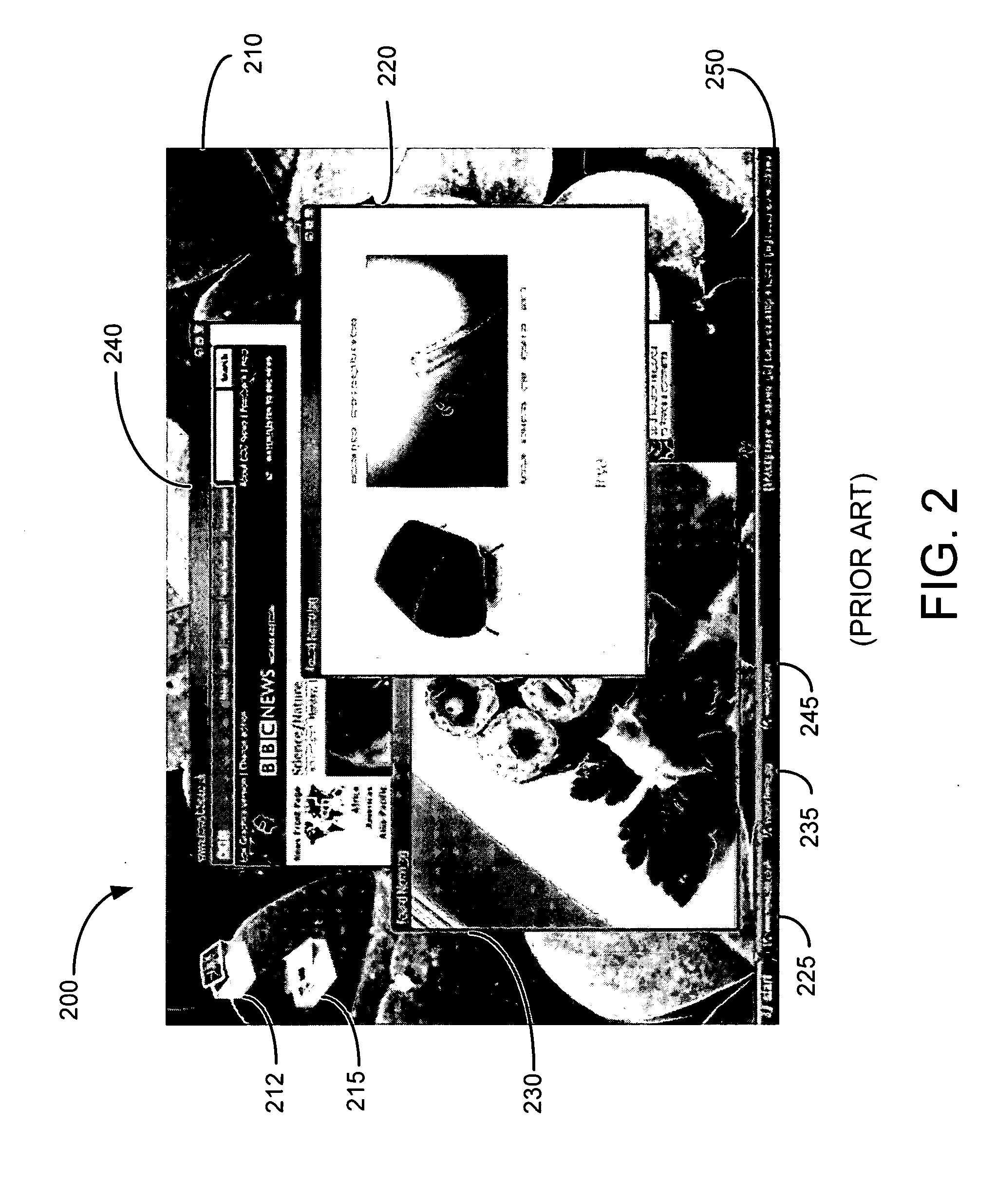
However, in certain instances windows may be rendered side by side such that the user looking at the display may have difficulty in determining which of the windows is active.
Both Windows XP and Mac OS 10 represent the active and inactive states in a rather subtle manner, which some users may not appreciate, which can lead to difficulty in determining which window is active.
While various visual techniques exist to represent the active and inactive states of UI elements, some users may not readily be able to determine which elements are active and inactive.

Method used


Image

  • System and method for visually expressing user interface elements
  • System and method for visually expressing user interface elements
  • System and method for visually expressing user interface elements

Examples


Embodiment Construction

[0019] In the following description of various illustrative embodiments, reference is made to the accompanying drawings, which form a part hereof, and in which is shown, by way of illustration, various embodiments in which the invention may be practiced. It is to be understood that other embodiments may be utilized and structural and functional modifications may be made without departing from the scope of the present invention.

Illustrative Operating Environment

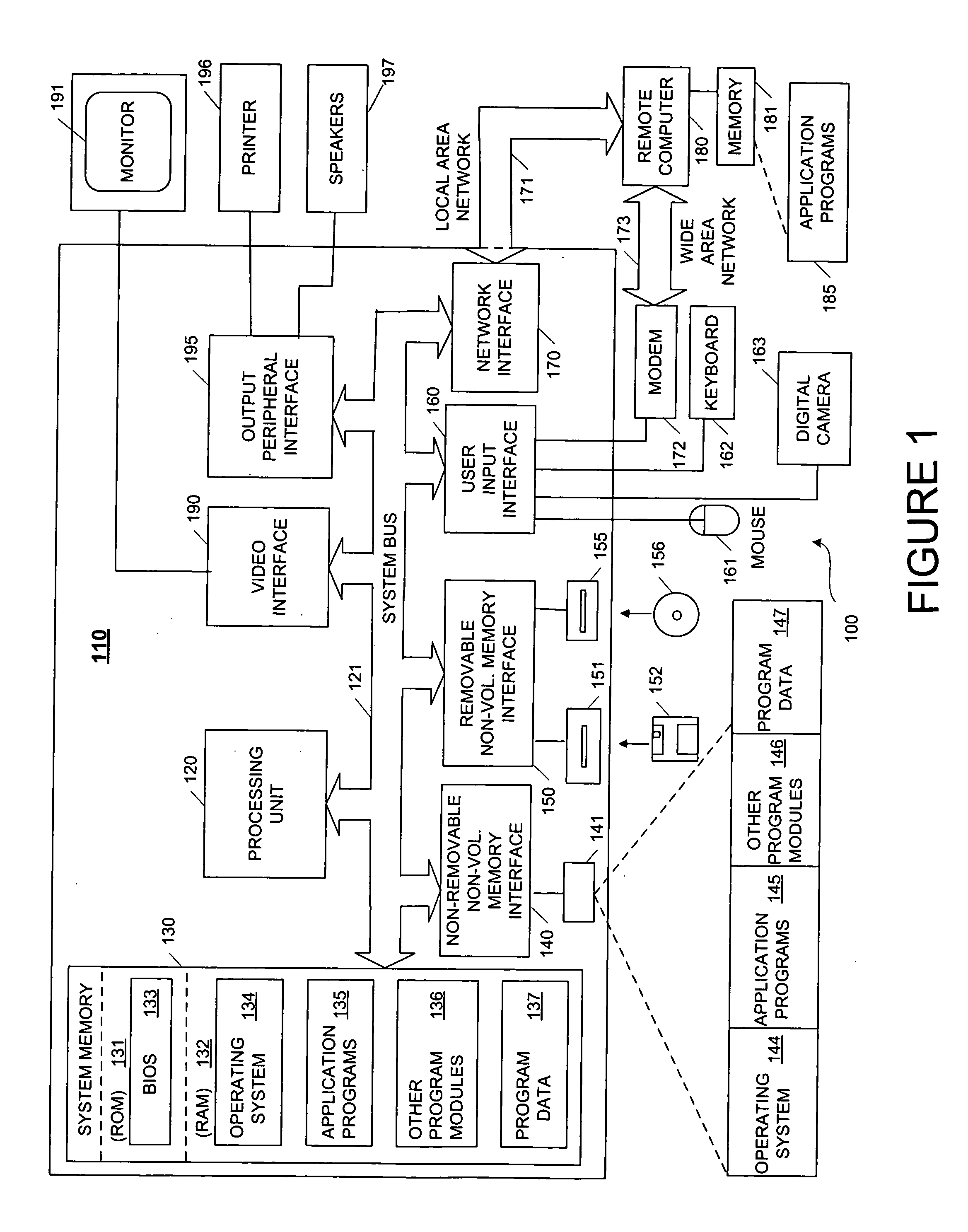
[0020]FIG. 1 illustrates an example of a suitable computing system environment 100 on which the invention may be implemented. The computing system environment 100 is only one example of a suitable computing environment and is not intended to suggest any limitation as to the scope of use or functionality of the invention. Neither should the computing system environment 100 be interpreted as having any dependency nor requirement relating to any one or combination of components illustrated in the exemplary computing system env...


PUM


Abstract

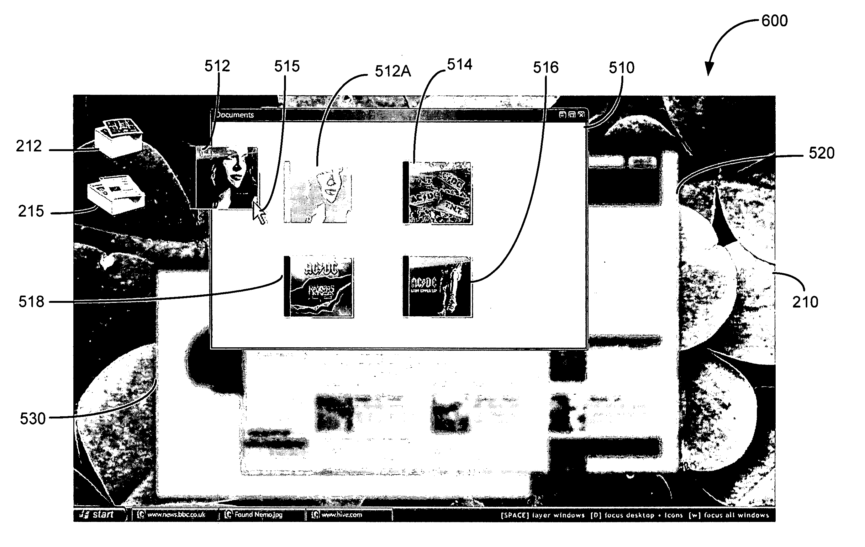
A method of visually expressing user interface elements on a display is provided which emphasizes those user interface elements which a user would be more interested in and deemphasizes those user interface elements which a user would be less interested in. Certain user interface elements, such as active elements, can be rendered in a sharp manner and be within a depth of field while other elements, such as inactive elements, can be rendered in a blurry manner and outside the depth of field.

Description

FIELD OF THE INVENTION [0001] Aspects of the present invention are directed generally to the presentation of user interface elements in or with an operating system. More particularly, aspects of the present invention are directed to a method and system for applying the concept of depth of field in the presentation of user interface elements. BACKGROUND OF THE INVENTION [0002] As the use of computers in both the workforce and personal life has increased, so has the desire to allow for easier use of them. Many operating systems today utilize a windows based configuration of application programs. Information is displayed on a display screen in what appears to be several sheets of paper. [0003] In existing environments application windows, the desktop and items on the desktop (e.g., icons representing folders, files, applications, etc.) form the core of user interface facilities for the graphical user interface (GUI) of computer systems. While these core facilities can vary in appearanc...

Claims


Application Information

Patent Timeline
IPC IPC(8): G06F9/00G06F3/00
CPCG06F3/0481
Inventor LINDSAY, DONALD J.LIGAMERI, MARK R.
Owner MICROSOFT TECH LICENSING LLC
Learn More