Stretcher, stretcher system and method for using the system

a stretcher and stretcher technology, applied in the field of stretcher system and stretcher method, can solve the problems of large physical burden of each officer to do the work of lifting up the bed, the bed and the total weight of a sick or injured person is substantially large, and the physical burden of each officer is considerably large. the effect of reducing the force to push the stretcher to the top of the support platform, reducing the physical burden of ambulance officers, and reducing the raised position of the bed

Inactive Publication Date: 2006-10-12
SHIN MEIWA IND CO LTD
View PDF26 Cites 93 Cited by
  • Summary
  • Abstract
  • Description
  • Claims
  • Application Information

AI Technical Summary

Benefits of technology

[0066] With the above stretcher system, the stretcher is automatically conveyed onto the support platform in laying the stretcher on the support platform. Therefore, not only the force to keep the raised position of the bed can be reduced but also the force to push in the stretcher to the top of the support platform can be reduced. As a result, the physical burdens of ambulance officers can be further reduced.

Problems solved by technology

Since the total weight of the bed and a sick or injured person is substantially great, a large force is required to lift up the bed.
The bed lifting work is normally done by two ambulance officers, but the physical burden for each officer to do that work is considerably large.
Therefore, it is difficult for an ambulance officer with less muscle to smoothly do the lifting work.
Therefore, they are likely to experience excessive physical burdens on their body parts (especially waists).
Hence, they often strained their body parts, particularly in the initial stage of the lifting work.
In addition, it is difficult that people exert large strength in stooping positions.
Therefore, it is difficult for ambulance officers to exert their full strength in the initial stage of the lifting work.
Therefore, its convenience is poor.
Further, since the repulsive force of the damper is not so much larger than the weight of a sick or injured person, it is hard to say that the physical burden of the lifting work is reduced enough.
In conclusion, it is difficult for any prior-art stretcher to extensively reduce the physical burden of the lifting work.
Since, however, the total weight of the stretcher on which the sick or injured person is laid is considerably large, a large physical burden is imposed on the ambulance officer when the stretcher is carried into the ambulance vehicle.
However, the transfer system cannot reduce the force to keep the bed raised.
Therefore, for any ambulance officer with less muscle who has difficulty in supporting the weight of the stretcher, it is difficult to carry out the carrying-in of the stretcher.
Therefore, even an ambulance officer with sufficient muscle was likely to strain his body part (especially the back) due to shock at the moment of release of the locking mechanism.

Method used


Image

  • Stretcher, stretcher system and method for using the system
  • Stretcher, stretcher system and method for using the system
  • Stretcher, stretcher system and method for using the system

Examples


embodiment 1

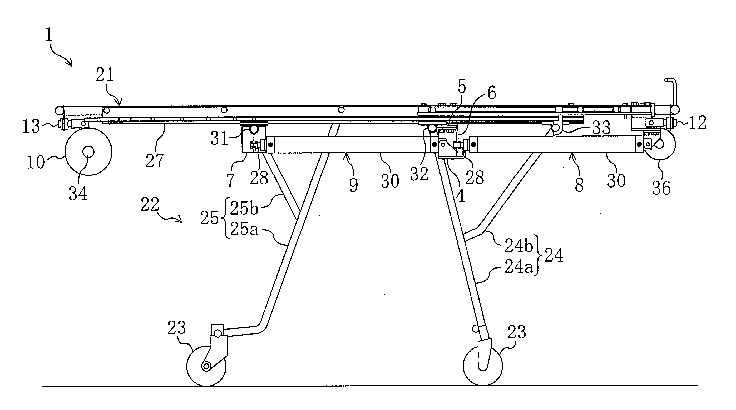
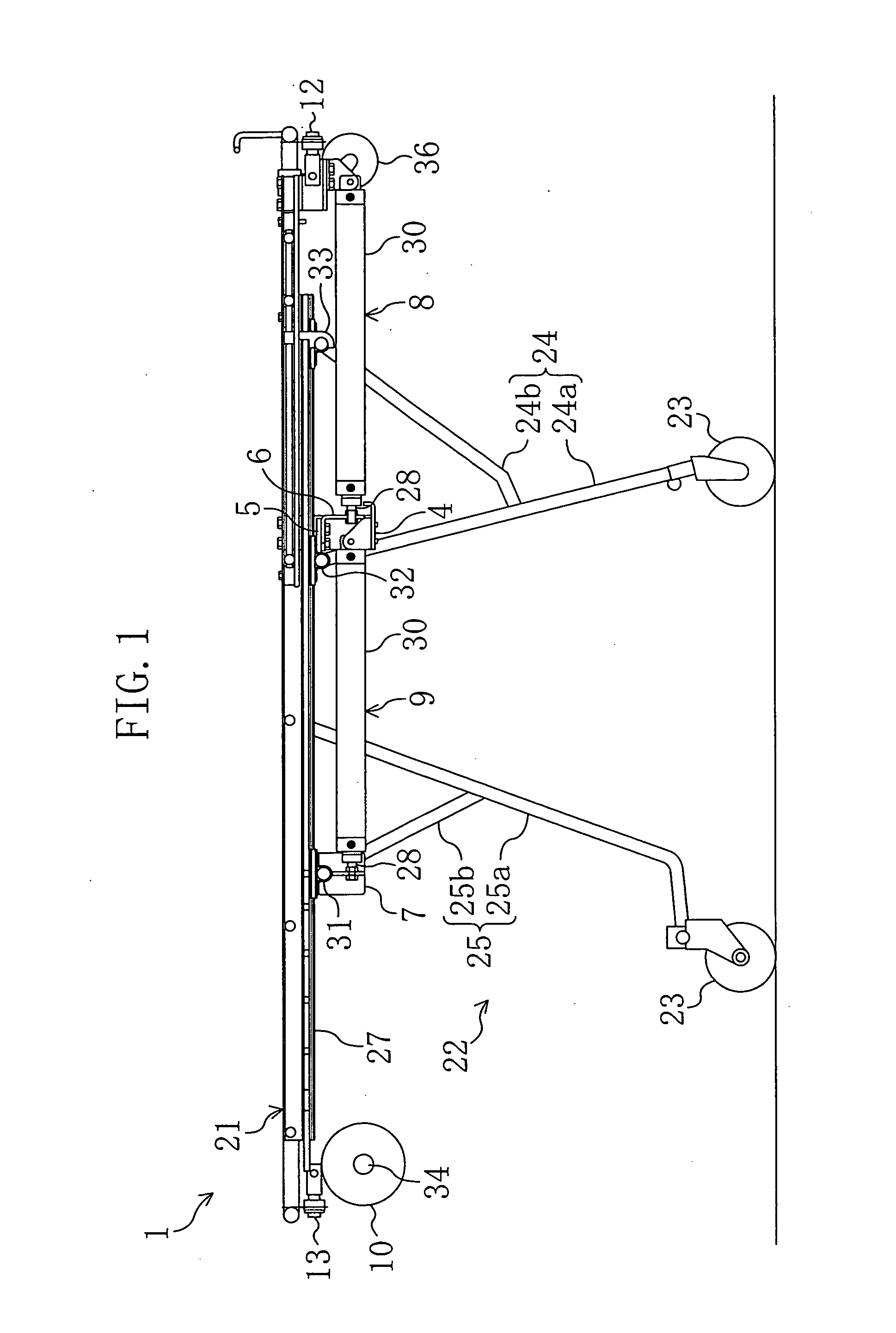
[0099] As shown in FIG. 1, a stretcher 1 of Embodiment 1 comprises a bed 21 on which a sick or injured person will be laid, and legs 22 foldably provided on the bed 21. Hereinafter, the side of the stretcher at which the head of a sick or injured person laid thereon comes (right side in FIGS. 1 to 3) is referred to as the head side while the other side at which the feet of the sick or injured person comes (left side in FIGS. 1 to 3) is referred to as the feet side.

[0100] The bed 21 is made up of a so-called framed structure and is formed by assembling a plurality of pipe members. The bed 21 supports, at some points on the structure of the pipe members, a litter (not shown) for riding a sick or injured person thereon. In this embodiment, the bed 21 is formed separately from the litter. It is a matter of course that the bed 21 may be equipped with a litter. In other words, the bed 21 may be formed integrally with the litter.

[0101] The legs 22 consist of two front legs 24 and two rea...

embodiment 2

[0138] Embodiment 2 is a modified form of the stretcher 1 of Embodiment 1, in which the pneumatic cylinders 8 and 9 are turned ON / OFF in conjunction with the unlocking levers. Further, this embodiment further includes a deactivation device for forcedly deactivating the ascent assist device.

[0139] As shown in FIG. 7, the stretcher 1 of Embodiment 2 has substantially the same structure as the stretcher 1 of Embodiment 1. Like Embodiment 1, a head-side unlocking lever 35a is provided at the head side of the bed 21 and a feet-side unlocking lever 35b is provided at the feet side of the bed 21. In Embodiment 2, a main switch 70 and a deactivation switch 71 both for the ascent assist device are also provided at the feet side of the bed 21. The main switch 70 and the deactivation switch 71 are both formed of dial (rotary) switches. The type of the switches 70 and 71, however, is not particularly limited.

[0140] As shown in FIG. 8, the piping system 50 for the stretcher 1 of Embodiment 2 i...

embodiment 3

[0155] As shown in FIGS. 11 and 12, a stretcher 1 of Embodiment 3 includes a bed 21 on which a sick or injured person will be laid, and legs 22 foldably mounted to the bed 21. Hereinafter, only different elements from Embodiment 1 will be described. The same elements as in Embodiment 1 are indicated by the same reference numerals and description is not given to them.

[0156] In these figures, the reference numeral 80 denotes a caster cover 80 attached to the distal end of each of the main legs 24a and 25a of the front and rear legs 24 and 25 to hold the caster 23 rollably. The caster cover 80 is formed with a projection 81 extending sideways (in the front to back direction of the paper in FIGS. 1 and 2).

[0157] The stretcher 1 of Embodiment 3 does not have the pneumatic cylinders 8 and 9 as described earlier. This stretcher 1 has a pneumatic cylinder 83 mounted at the head side of the bed 21 and a pneumatic cylinder 84 mounted at the feet side of the bed 21. Each pneumatic cylinder 8...


PUM


Abstract

A stretcher 1 comprises a bed 21 on which a sick or injured person will be laid, legs 22 foldably provided on the bed 21, casters 23 provided at the legs 22, respectively, a tank 10 for storing high-pressure gas, pneumatic cylinders 8 and 9, and intake switches 11 and 13. When the intake switches 11 and 13 are turned ON, high-pressure gas is introduced from the tank 10 into the pneumatic cylinders 8 and 9 so that piston rods 28 are retracted. Thus, the legs 22 are given forces toward deployment so that the bed 21 is given an ascending force.

Description

TECHNICAL FIELD [0001] This invention relates to a stretcher, a stretcher system and a method for using a stretcher. BACKGROUND ART [0002] When ambulance officers carry a sick or injured person into an ambulance vehicle, a stretcher with foldable legs is conventionally used. Stretchers of such kind are each made up of a bed on which a sick or injured person will be laid and foldable legs, and typically used by two ambulance officers as follows. [0003] After the ambulance officers transfer the stretcher to a site at which a sick or injured person exists, they fold up the legs of the stretcher, lower the bed to the ground and then lay the sick or injured person on the bed. Thereafter, both the ambulance officers lift up the bed at a time with one holding the head side of the bed and the other holding the feet side thereof. With ascent of the bed, the legs automatically deploy by self-weight. As a result, the stretcher stands up. When the bed is raised to a predetermined level, the leg...

Claims


Application Information

Patent Timeline
Patent Type & Authority Applications(United States)
IPC IPC(8): A61G7/10A61G1/056A61G3/00
CPCA61G3/00A61G1/056
Inventor HOSOYA, TAKASHIKIMURA, SHOTAROKARA, KEIICHIROSHIRAI, HIROAKI
Owner SHIN MEIWA IND CO LTD
Why Eureka
Try Eureka