Eureka AIR delivers breakthrough ideas for toughest innovation challenges, trusted by R&D personnel around the world.

Process for forming a connector for tube and pipe fittings

a technology of connectors and pipe fittings, which is applied in the direction of branching pipes, mechanical equipment, other domestic objects, etc., can solve the problems of unable to produce large volumes of parts, stress on connections, and inability to provide support for tubes in the pivoting region of movemen

Inactive Publication Date: 2006-10-12
TRU FIT ALIGNMENT SOLUTIONS
View PDF22 Cites 6 Cited by
  • Summary
  • Abstract
  • Description
  • Claims
  • Application Information

AI Technical Summary

Benefits of technology

The present invention provides a process for forming a fitting for coupling parts, such as pipes, tubes, or rods, that allows for a defined pivoting range of movement of the parts relative. This eliminates the need for bending the parts, reducing stress and improving tolerance between the two objects being connected. The invention also allows for telescoping tube configurations between the objects being connected and enables a rounded end on a first element, a conical bore in a connector nut, and a flared end on a second element to slidably contact the rounded end. The invention also includes a connector that includes a rounded end on a first element, a conical bore in a connector nut, and a flared end on a second element to slidably contact the rounded end. The technical effects of the invention include improved flexibility, reduced stress, and improved tolerance between parts.

Problems solved by technology

Moreover, as engineering variances and tolerances make it impossible to produce two tubes, pipes, or rods that are exactly alike, such production is likewise impossible when producing large volumes of parts.
Even with the standard tolerances given in the manufacturing process, stresses arise when connections are made.
This arrangement, while allowing pivoting movement, does not provide support for the tubes in the region of the pivoting movement.
As with the above-described patent to Krenz, the clamp of Yamaga does not provide support for the gas pipes in the pivoting region.
Once again, the housing of Aaron, III does not provide support for the pivoting pipe, which could result in the failure of the weld, and, therefore, the entire coupling.

Method used


Image

  • Process for forming a connector for tube and pipe fittings
  • Process for forming a connector for tube and pipe fittings
  • Process for forming a connector for tube and pipe fittings

Examples


Embodiment Construction

[0049] The particulars shown herein are by way of example and for purposes of illustrative discussion of the embodiments of the present invention only and are presented in the cause of providing what is believed to be the most useful and readily understood description of the principles and conceptual aspects of the present invention. In this regard, no attempt is made to show structural details of the present invention in more detail than is necessary for the fundamental understanding of the present invention, the description taken with the drawings making apparent to those skilled in the art how the several forms of the present invention may be embodied in practice.

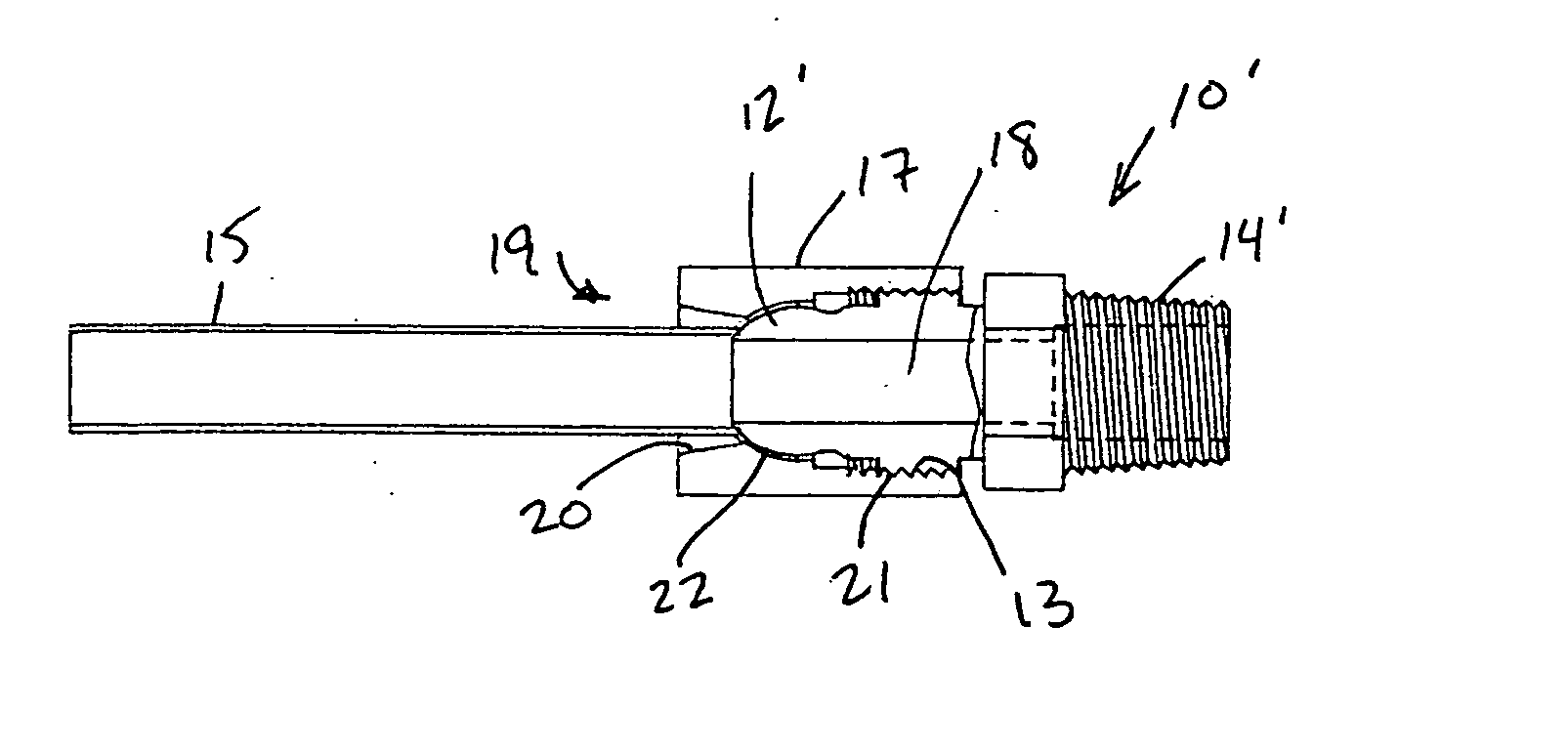
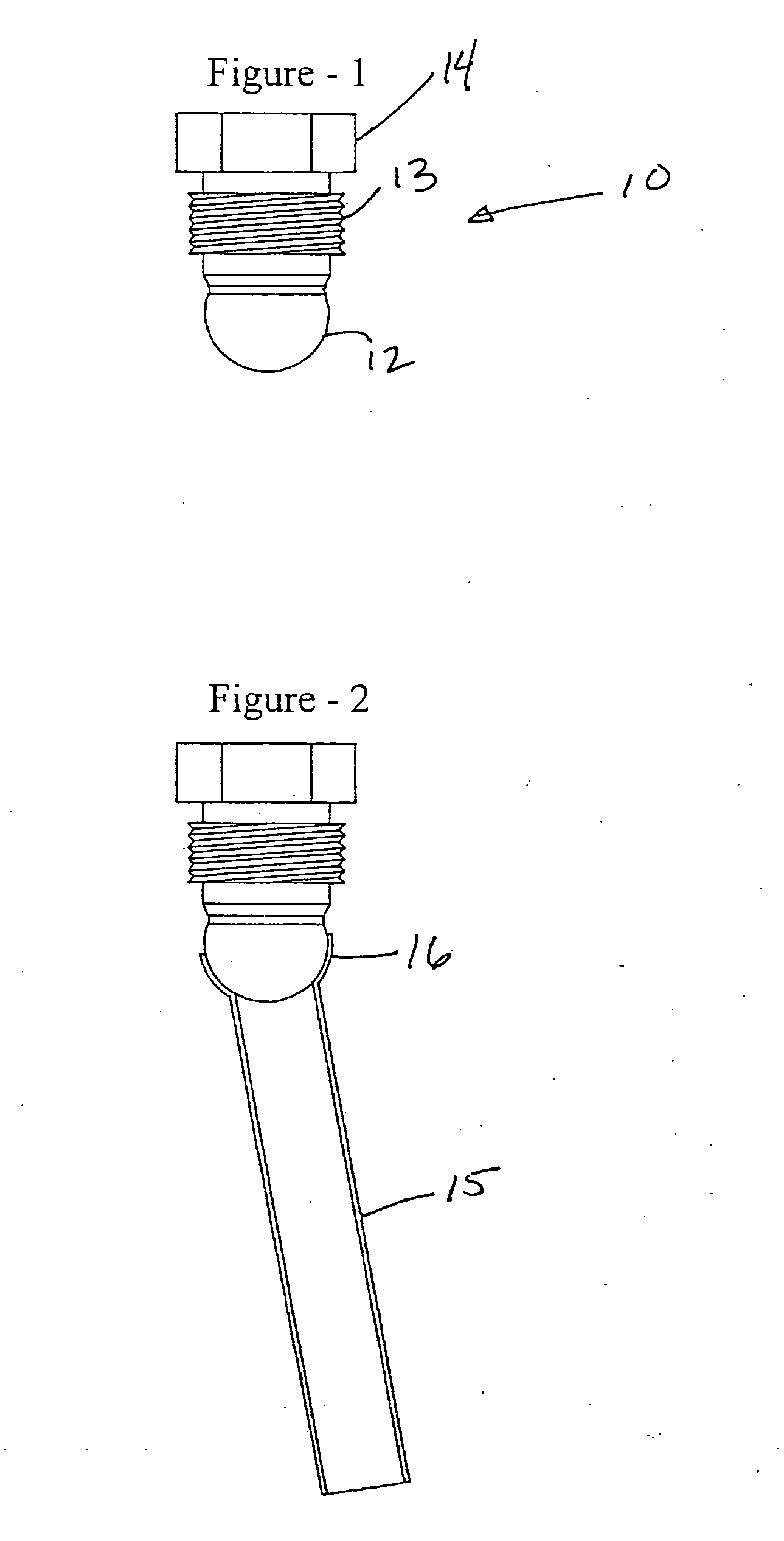
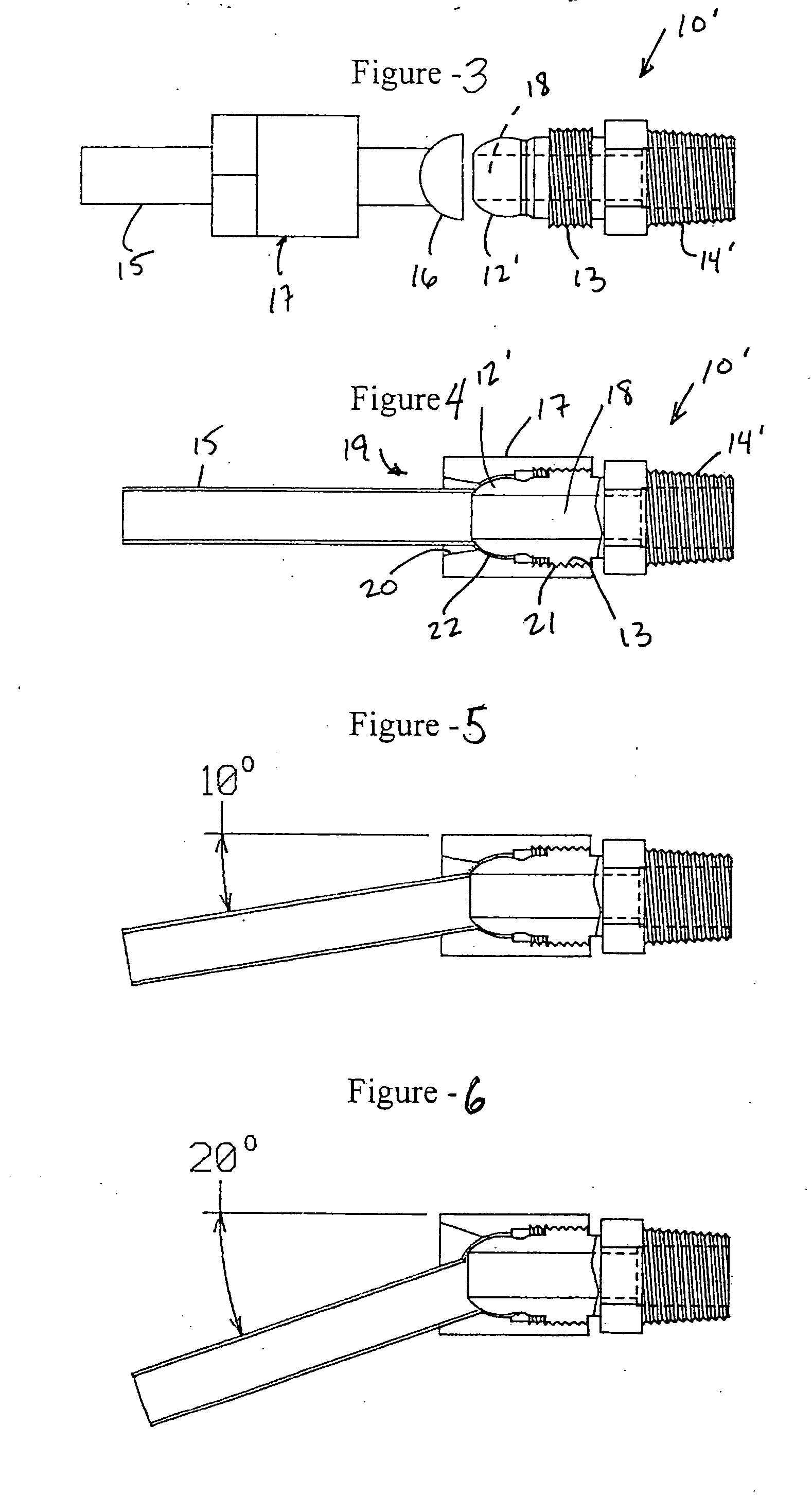
[0050]FIG. 1 shows a male plug fitting 10 having a spherical (circular) end 12. While FIG. 1 does not show a through hole extending through male plug fitting 10, such a design is contemplated and advantageous. Male plug fitting 10 also includes male threads 13 for connection to a coupling nut (not shown) and a female co...


PUM

PropertyMeasurementUnit
angleaaaaaaaaaa
angleaaaaaaaaaa
pivot angleaaaaaaaaaa

Abstract

Connector that includes a first element having a threaded portion and a rounded end, a second element having an end structured to slidably contact the rounded second end of the first element, and a third element having a conical bore. The second element extends through the conical bore for movement within the conical bore, and a threaded end structured and arranged to mate with the threaded portion of the first element. The instant abstract is neither intended to define the invention disclosed in this specification nor intended to limit the scope of the invention in any way.

Description

CROSS-REFERENCE TO RELATED APPLICATION [0001] The present application is a divisional of U.S. patent application Ser. No. 10 / 855,424 filed May 28, 2004, the disclosure of which is expressly incorporated by reference herein in its entirety.BACKGROUND OF THE INVENTION [0002] 1. Field of the Invention [0003] The present invention relates to a process for forming a fitting for connecting tubes, pipes, and / or solid rods together. Moreover, when the tubes or pipes are utilized for transmitting fluids, e.g., liquids or gases, the connections provide sufficient sealing to prevent leakage of the fluid. [0004] 2. Discussion of Background Information [0005] Prior designs allow for one directional alignment at a point of contact between the fitting and the mating part. If it were necessary or desired to connect, via a tube, pipe, or rod, two objects having connector mounts that are offset from each other, i.e., not positioned in a straight line, some bending of the tube, pipe, or rod would be r...

Claims


Application Information

Patent Timeline
Patent Type & Authority Applications(United States)
IPC IPC(8): B23P17/00F16L27/04F16L27/047F16L41/02
CPCF16L27/047Y10T29/49428F16L41/021
Inventor PORTER, ARTHUR
Owner TRU FIT ALIGNMENT SOLUTIONS
Why Eureka
Eureka Blog
Learn More