Tubing connector and method of sealing tubing sections

a technology of connectors and tubing, which is applied in the direction of hose connections, manufacturing tools, and borehole/well accessories, etc., can solve the problems of pins drawing inwardly out, maintaining a seal between pins,

Inactive Publication Date: 2011-03-01
WEATHERFORD TECH HLDG LLC
View PDF189 Cites 20 Cited by
  • Summary
  • Abstract
  • Description
  • Claims
  • Application Information

AI Technical Summary

Benefits of technology

[0013]Preferably, the connector comprises a connector for expandable tubing sections. The seal profile may be adapted to be urged into sealing engagement with the other portion on expansion of the seal profile alone, or during expansion of the first and second portions. The first and second portions, and thus the connector, may be adapted to define a substantially constant internal diameter post-expansion. This may avoid any step, upset or the like causing a relative reduction in internal diameter of the connector following expansion.
[0020]Preferably, a wall of the first and / or second portion having the seal profile is of a greater cross-sectional thickness in the region of the seal portion than axially adjacent areas of the respective portion or portions. This may ensure that the seal portion does not reduce the integrity of the connection post-expansion.
[0023]The seal profile may be provided on or in a recess, such as an indent, channel, groove, fold, crinkle or slot in a wall of the respective first and second portion, and may be adapted to be urged radially outwardly on expansion, to at least partly protrude proud of the recess. This allows the seal profile to be moved between a position out of sealing engagement with, and a position in sealing engagement with the other one of the first and second portions. Accordingly, this may allow the seal profile to be moved between a position in sealing engagement with, and a position in enhanced sealing engagement with the other one of the first and second portions.
[0032]Alternatively, the connector may be for non-expandable tubing sections and may, for example, provide an enhanced seal between non-expandable tubing sections.
[0037]Preferably, the tubing is expandable and the tubing sections comprise expandable tubing sections. The tubing sections may be adapted to define a substantially constant internal diameter post expansion. This may avoid any steps, upsets or the like restricting the tubing bore.

Problems solved by technology

Maintaining a seal between the pin and box portions post expansion can be problematic due to elastic recovery, which tends to cause the pin to draw inwardly out of contact with the box.

Method used


Image

  • Tubing connector and method of sealing tubing sections
  • Tubing connector and method of sealing tubing sections
  • Tubing connector and method of sealing tubing sections

Examples


Embodiment Construction

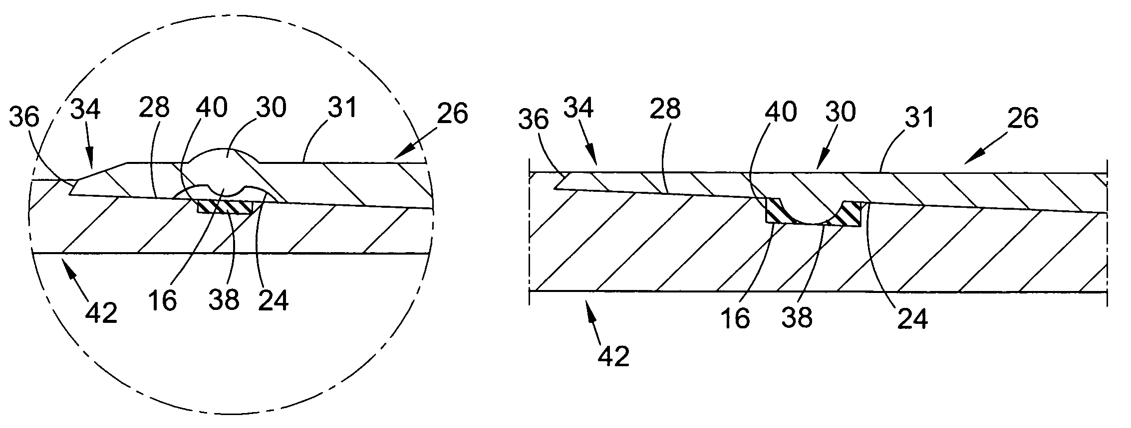
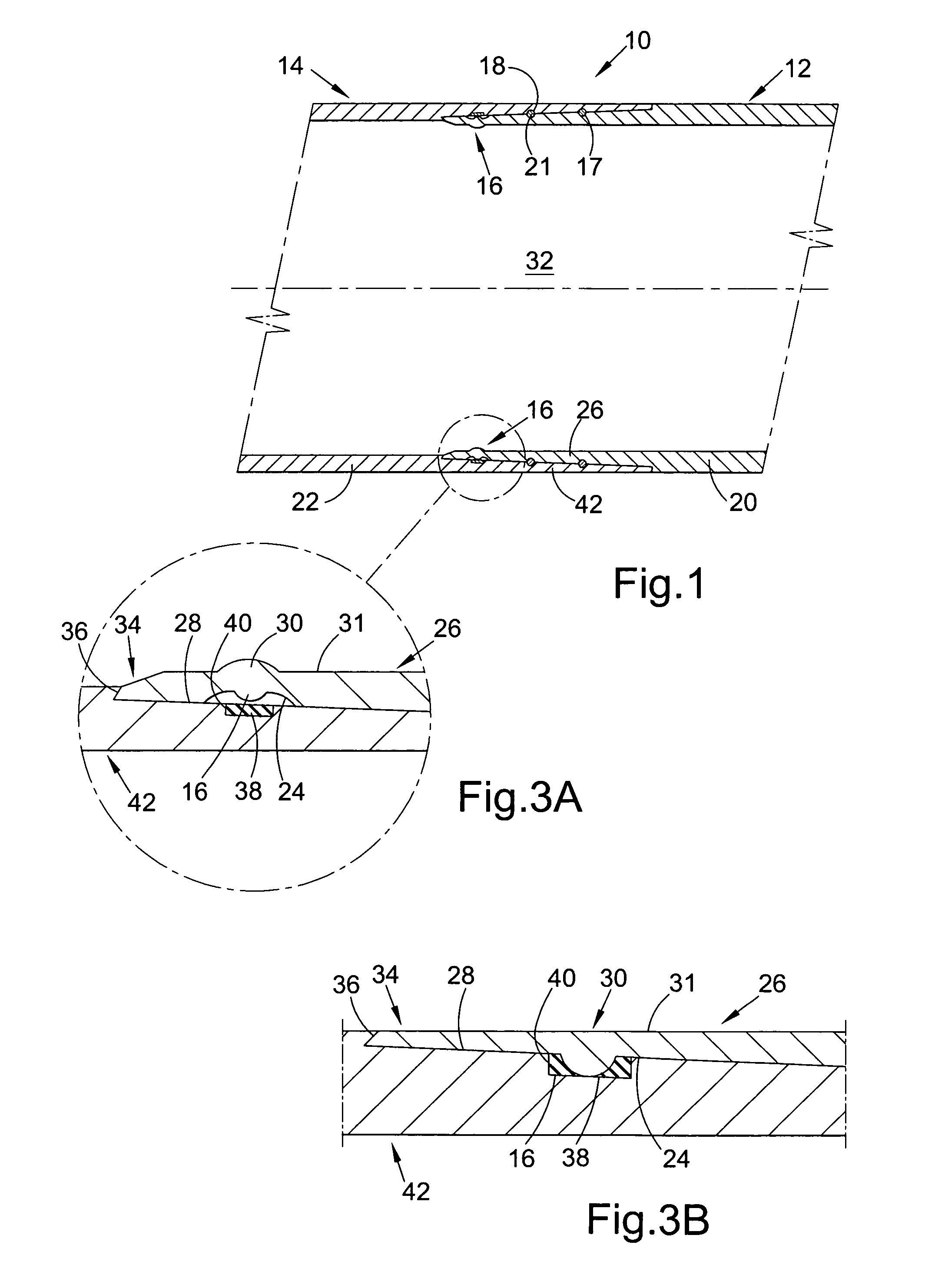
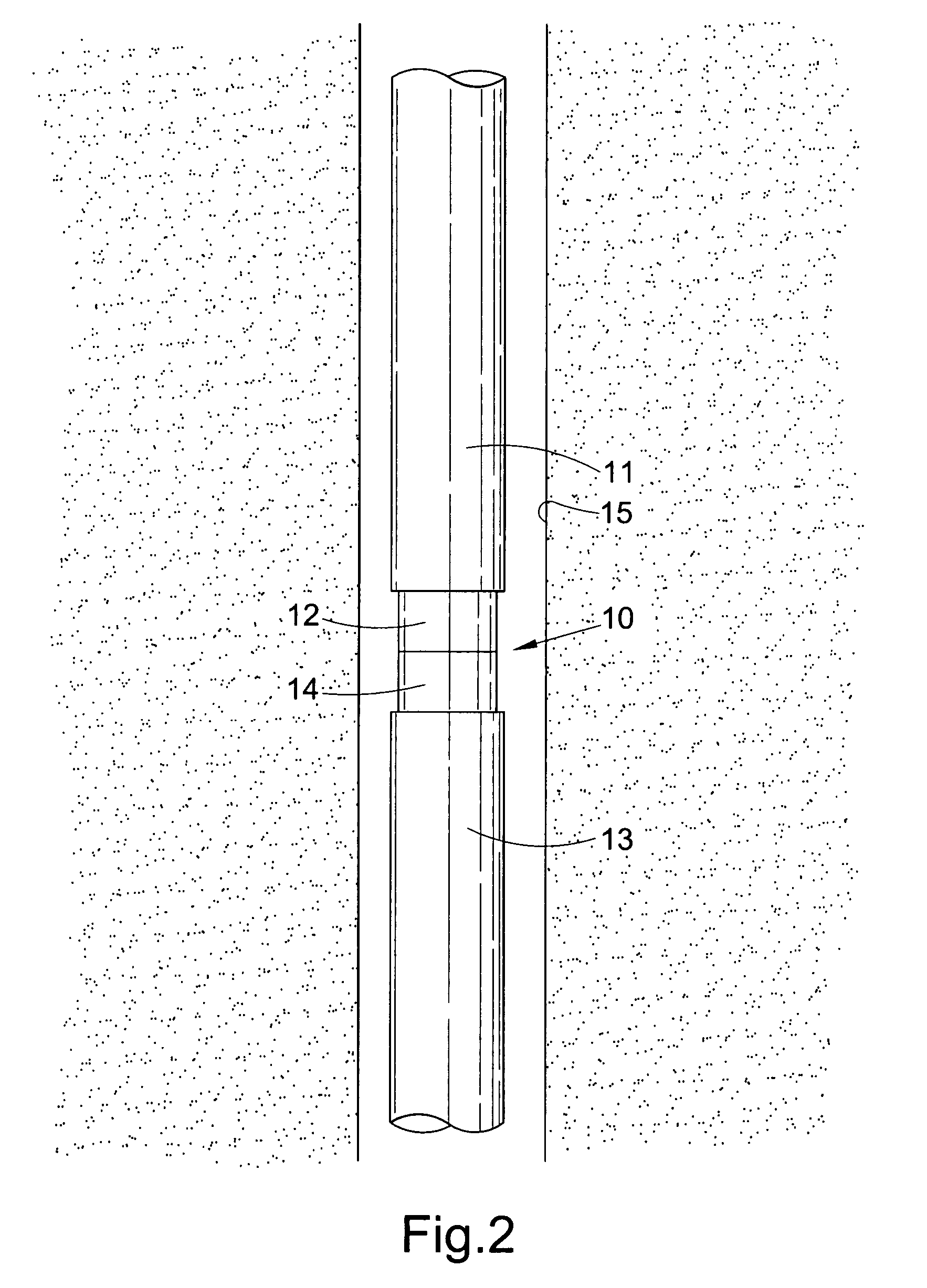
[0064]Turning firstly to FIG. 1, there is shown a longitudinal sectional view of a connector for expandable tubing in accordance with a preferred embodiment of the present invention, the connector indicated generally by reference numeral 10. The connector 10 is suitable for coupling expandable tubing sections 11, 13 (FIG. 2) together at surface, prior to location of the tubing sections in the downhole environment, and is shown in FIG. 1 prior to expansion. The tubing sections 11, 13 are shown coupled together and located in a borehole 15 in FIG. 2. The tubing sections may comprise solid or continuous-walled expandable tubing such as casing or liner, as well as other types of expandable tubing, such as slotted tubing and sand exclusion assemblies. The tubing sections 11, 13 shown in FIG. 2 comprise sections of the Applicant's commercially available ESS (Trademark) sandscreen.

[0065]The connector 10 comprises first and second portions 12, 14 adapted to be provided on respective expanda...


PUM

PropertyMeasurementUnit
yield strengthaaaaaaaaaa
dimensionsaaaaaaaaaa
diameteraaaaaaaaaa

Abstract

There is disclosed a connector for tubing, in particular, expandable tubing sections. There is also disclosed a method of sealing a connection between tubing sections, in particular, expandable tubing sections.In one embodiment of the invention, a connector (10) is disclosed which is suitable for coupling expandable tubing sections (11,13) together. The connector (10) comprises first and second portions (12,14) adapted to be provided on respective expandable tubing sections (11, 13), at least one of the portions (12,14) including a seal profile (16) which is adapted to be urged into sealing engagement with the other portion (12,14) on expansion thereof.

Description

CROSS-REFERENCE TO RELATED APPLICATIONS[0001]This application claims benefit of a British patent application serial number GB 0311721.5, filed May 22, 2003, which is herein incorporated by reference.BACKGROUND OF THE INVENTION[0002]1. Field of the Invention[0003]The present invention relates to a connector for tubing. In particular, but not exclusively, the present invention relates to the sealing of a connector for expandable downhole tubing sections.[0004]2. Description of the Related Art[0005]In the oil and gas exploration and production industry, expandable tubing has been developed and has a variety of uses. These include expandable borehole casing and liner, and expandable sand exclusion based tubing assemblies or sandscreens, such as that disclosed in International patent publication no WO97 / 17524 (Shell), and as sold under the ESS Trademark by the present applicant.[0006]Expandable tubing offers a number of advantages over conventional borehole tubing, as the expandable tubi...

Claims


Application Information

Patent Timeline
Patent Type & Authority Patents(United States)
IPC IPC(8): B21D33/00B21D39/00E21B23/00F16L25/00F16L41/00E21B43/10F16L13/14F16L13/16
CPCE21B43/106F16L13/168Y10T29/49911Y10T29/49908Y10T29/49428Y10T29/4994
Inventor MAGUIRE, PATRICK GLEN
Owner WEATHERFORD TECH HLDG LLC
Why Eureka
Try Eureka