Air bag cover with articulated tear seam

a technology of airbag cover and tear seam, which is applied in the direction of vehicle components, pedestrian/occupant safety arrangements, vehicular safety arrangments, etc., can solve the problems of reducing cracking or tearing of the module cover, and the riveting used to couple the cover to the airbag housing requires very labor-intensive assembly procedures, so as to reduce the integrity of the airbag module and reduce the force. , the effect of less for

Inactive Publication Date: 2006-02-07
KEY SAFETY SYST
View PDF10 Cites 19 Cited by
  • Summary
  • Abstract
  • Description
  • Claims
  • Application Information

AI Technical Summary

Benefits of technology

[0004]The branched shapes of the tear seams require more energy and time to tear, thus the air bag must be deployed with a very high force for it to deploy and inflate rapidly enough to serve as a crash restraint. In addition, the high force used during deployment can cause the cover to break in high stress regions, resulting in reduced integrity of the air bag module. Additionally, the high deployment forces can lead to cracking or tearing of the module cover. Furthermore, these tear seam designs limit the area of opening in the cover and tend to cause the air bag to deploy straight outward rather than outward and to the sides. By allowing the air bag to expand quickly to the sides, the air bag inflates with less force and more efficiency.
[0005]The rivets used to couple the cover to the air bag housing require very labor intensive assembly procedures. Further, the rivets produce a high stress concentration interface between the cover and the air bag mounting plate, which can provide crack initiation sites. Air bag modules having an H-shaped or U-shaped cover experience significant stresses on the door hinges caused by inertial forces from the rotating of the door mass. As such, it is desirable to provide a cover design that enables the air bag cover to be retained without rivets with ensured integrity after deployment. It is also desirable to provide a tear seam that ruptures more rapidly and that will deploy in response to a lower inflation force.
[0006]The present invention provides a steering wheel assembly that receives a fastenerless air bag cover assembly that increases the integrity of the air bag module after deployment. This assembly employs a housing with a projection and a steering wheel armature configured to receive the projection. The cover is retained between the housing and the steering wheel armature. In addition, the present invention provides an air bag cover with a tear seam that permits the air bag to deploy more efficiently with less stress to the module. Specifically, the cover has a circular center from which at least one tear seam radiates. The tear seam ends at an articulated terminus.

Problems solved by technology

In addition, the high force used during deployment can cause the cover to break in high stress regions, resulting in reduced integrity of the air bag module.
Additionally, the high deployment forces can lead to cracking or tearing of the module cover.
Furthermore, these tear seam designs limit the area of opening in the cover and tend to cause the air bag to deploy straight outward rather than outward and to the sides.
The rivets used to couple the cover to the air bag housing require very labor intensive assembly procedures.
Air bag modules having an H-shaped or U-shaped cover experience significant stresses on the door hinges caused by inertial forces from the rotating of the door mass.

Method used


Image

  • Air bag cover with articulated tear seam
  • Air bag cover with articulated tear seam
  • Air bag cover with articulated tear seam

Examples


Embodiment Construction

[0015]The following description of the preferred embodiments is merely exemplary in nature and is in no way intended to limit the invention, its application, or uses.

[0016]The present invention is generally related to an air bag cover for a steering wheel assembly. However, it is to be understood that the principles embodied herein are equally applicable to other types of applications involving air bags with covers.

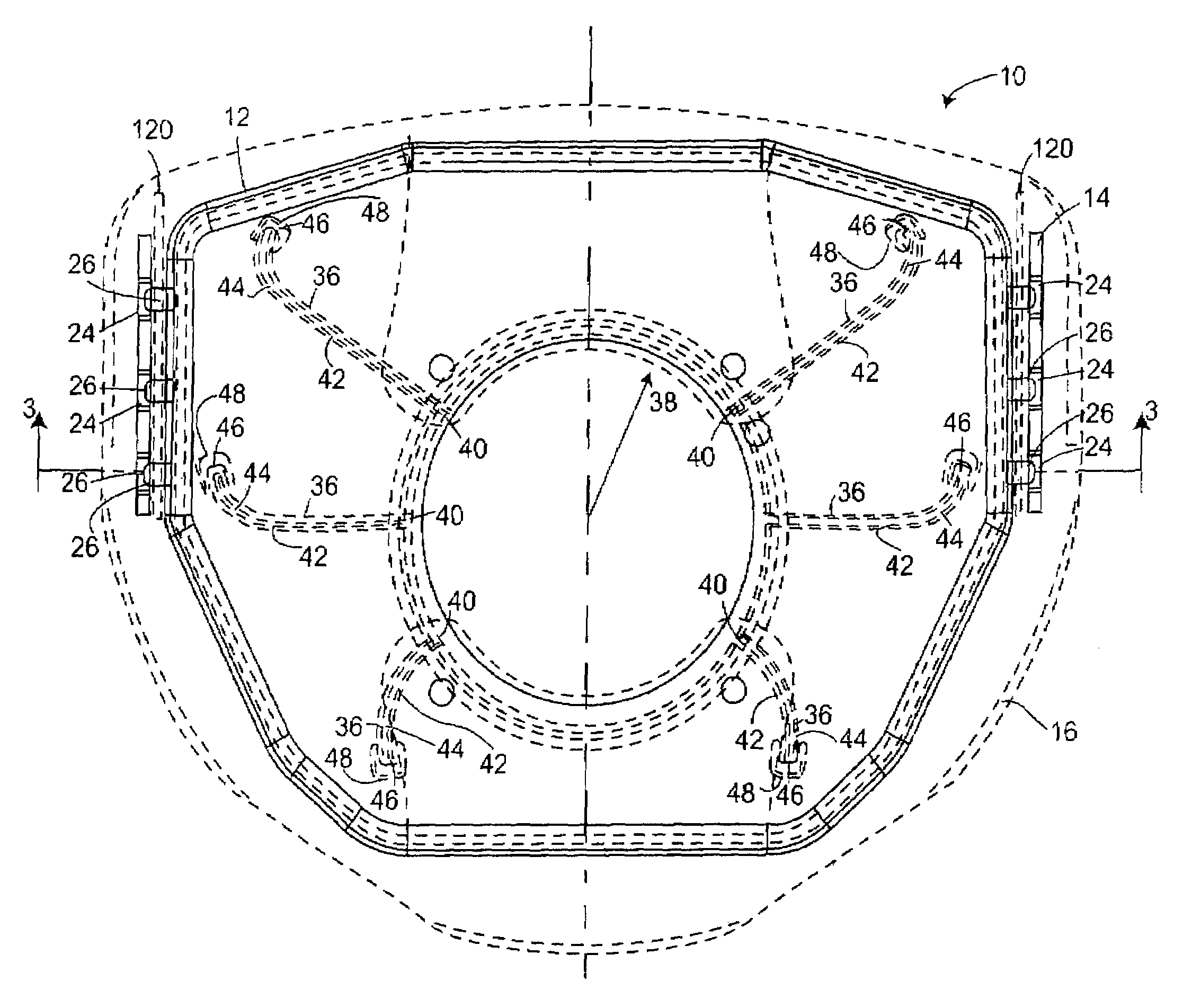
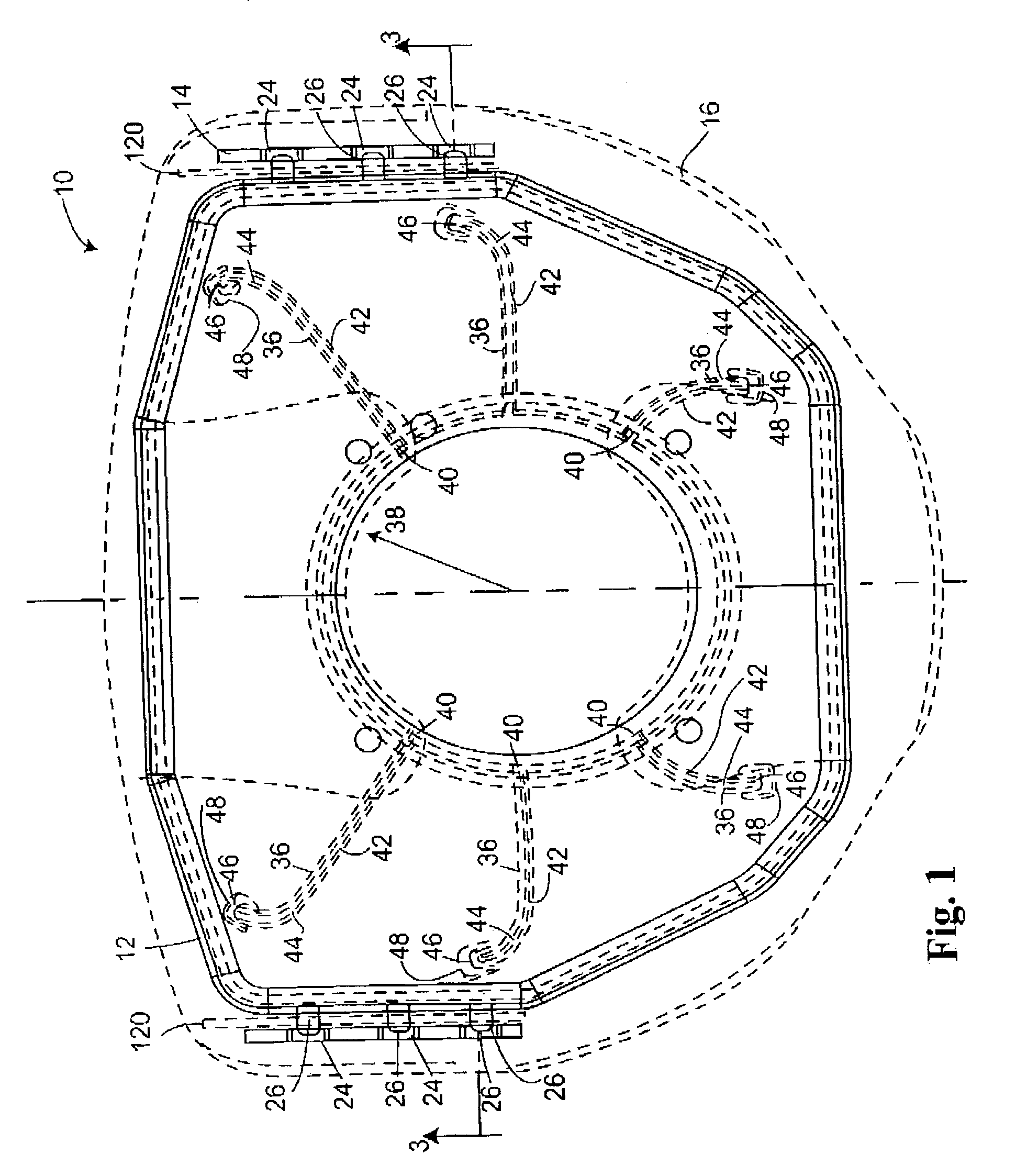
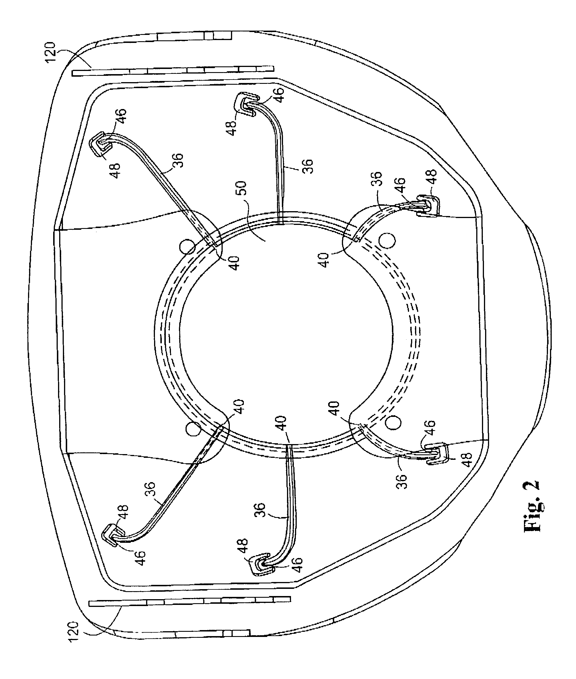
[0017]Referring generally to FIGS. 1 through 2, an air bag module 10 is shown. The air bag module 10 includes a housing 12 coupled to a steering wheel armature 14. A cover 16 is retained by both the housing 12 and the steering wheel armature 14. The cover 16, which is shown in phantom for clarity, defines a plurality of retaining apertures 34, which are used to mount the cover 16 to the housing 12. The air bag module 10 also includes an inflator or gas generator (not shown) of known type to provide inflation gases to the folded air bag or cushion (not shown).

[0018]The ste...


PUM


Abstract

A steering wheel assembly having a fastenerless air bag module assembly is disclosed. This assembly employs a housing with a projection and a steering wheel armature configured to receive the projection. The cover is retained between the housing and the steering wheel armature. Furthermore, the present invention provides a steering wheel cover with a tear seam that permits the air bag to deploy more efficiently with less damage to the occupants.

Description

BACKGROUND AND SUMMARY OF THE INVENTION[0001]The present invention relates generally to steering wheel assemblies having air bags and, more particularly, to a cover for an air bag of a steering wheel assembly.[0002]Air bags typically are located beneath a cover of a steering wheel assembly. Historically, the steering wheel was attached to the vehicle and then the air bag module, which included a cover attached over the air bag, was attached.[0003]A steering wheel and air bag assembly includes a cover, a steering wheel armature and an air bag. Most covers are formed of a synthetic plastic material that is positioned over the air bag cushion. The cover is generally attached to the steering wheel assembly by rivets. In order for the air bag to deploy properly, it is necessary to provide a thinned portion for the air bag to break through the cover. Typically, the thinned regions included tear seams located in the cover that had generally been either H-shaped, I-shaped, U-shaped or branc...

Claims


Application Information

Patent Timeline
Patent Type & Authority Patents(United States)
IPC IPC(8): B60R21/16B60R21/20B60R21/203B60R21/215B60R21/217
CPCB60R21/2035B60R21/217B60R21/21656
Inventor FORD, BRIAN C.LANGBEEN, LAWRENCE R.
Owner KEY SAFETY SYST
Why Eureka
Try Eureka