Packaging Article

a technology for packaging and beverage containers, applied in the field of beverage containers, can solve the problems of not being able to achieve the practical solution to the problem, and yet no beverage container that fulfils these aims has been produced, so as to prevent the egress of gas, prevent the contamination of beverage, and prevent the effect of staleness

Inactive Publication Date: 2008-12-11
DUBOIS LIMITED (GB)
View PDF9 Cites 20 Cited by
  • Summary
  • Abstract
  • Description
  • Claims
  • Application Information

AI Technical Summary

Benefits of technology

[0015]The foil is preferably secured to the container in a manner capable of withstanding elevated internal pressures, e.g. of 1-2 bar (as might arise if a carbonated drinks container is subject to high temperatures). As well as preventing the egress of gas, the foil also protects the container from ingress of gas, so helps prevent contamination of the beverage and prevent it becoming stale. With such a foil, the beverage container can have a shelf-life of at least 9 months (as typically required for beers and other carbonated drinks sold in containers).
[0016]The foil may also provide tamper evidence in that if the foil is intact it provides the consumer with reassurance that the product has not been tampered with or previously opened or otherwise exposed to the external atmosphere. This function is further enhanced if the cap is formed of a transparent material.
[0017]Althoug

Problems solved by technology

Despite the tremendous advantages that such a beverage container would provide for drinks suppliers, container manufacturers and consumers alike, no successful beverage container that fulfils these aims

Method used


Image

  • Packaging Article
  • Packaging Article
  • Packaging Article

Examples


second embodiment

[0051]The second embodiment shown in FIGS. 4 and 5, comprises a container body 21, a foil 22 covering the mouth of the container body 21 and a cap 23 fitted onto the container body 21 over the foil 22.

[0052]The container body has a lip 24 and the foil 22 extends over the lip 24. The cap is preferably a snap-fit plastic cap but a metal cap may also be used which can be crimped over the lip 24.

[0053]The cap 23 is shaped so as to be a snap-fit over the lip 24 of the container body 21. Alternatively, the cap 23 may be shrunk fit onto the container body 21. The foil 22 is preferably secured to the lip 24 by localised induction heating to melt a plastic layer on the underside of the foil and so weld it to the lip 24. Alternatively, or additionally, the foil 22 is crimped over the edge of the lip 24. If required, it may also be sealed to the external surface of the container. The foil is also preferably secured to the cap 23 by localised heating to melt a plastic layer on the upperside of ...

fourth embodiment

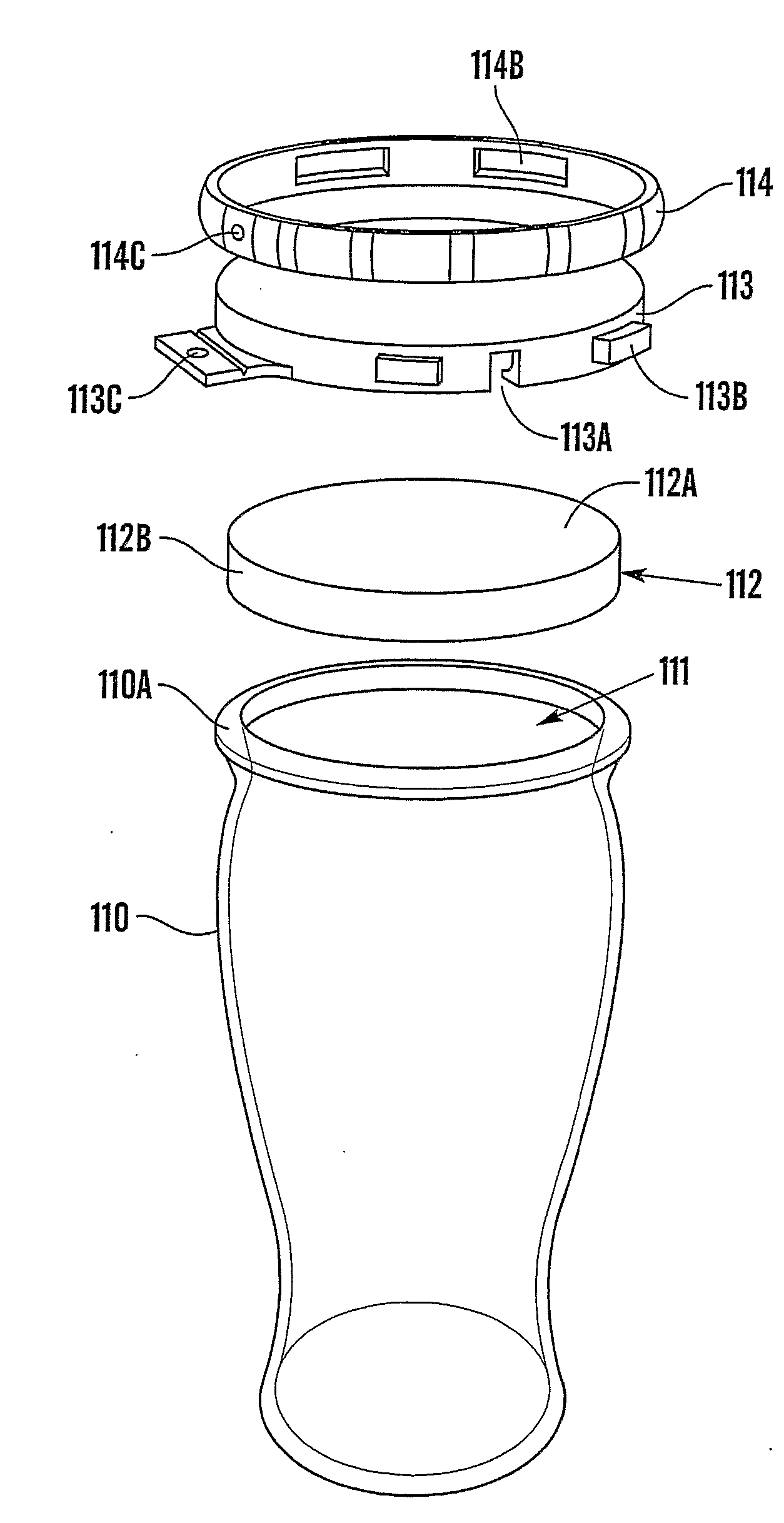
[0062]FIG. 8 shows the invention in which a foil is used to seal a wide-mouth container in conjunction with closure means or a cap which protects and / or re-enforces the foil.

[0063]FIG. 8A shows a container 110 with an opening 111 and closure means comprising a foil 112, cap 113 and collar 114.

[0064]The container is shaped to resemble a beer glass and has a lip 110A around its opening 111. The foil has a top part 112A and skirt 112B. The cap 113 includes one or more gaps 113A in its periphery, has thread-like formations 113B on its external surface and preferably has tamper evident clips 113C attached thereto by a living hinge and carrying a projection. The collar 114 comprises threadlike formations 114B on its inner surface for engaging with the thread-like formations 113B of the cap and a recess and hole 114C for receiving each clip and projection 113C.

[0065]As shown in FIG. 8B, the foil 112 is held in contact with the lip 110A by the cap 113. The cap 113 has an internal projecting...

fifth embodiment

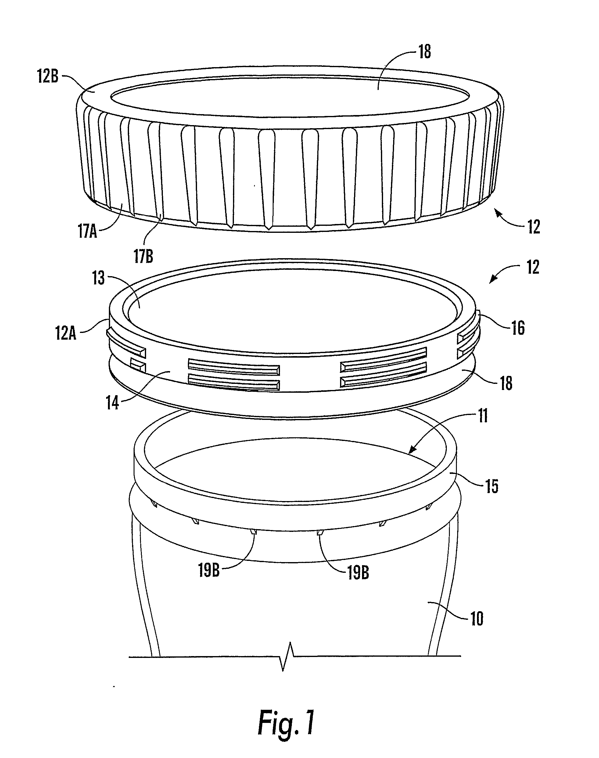
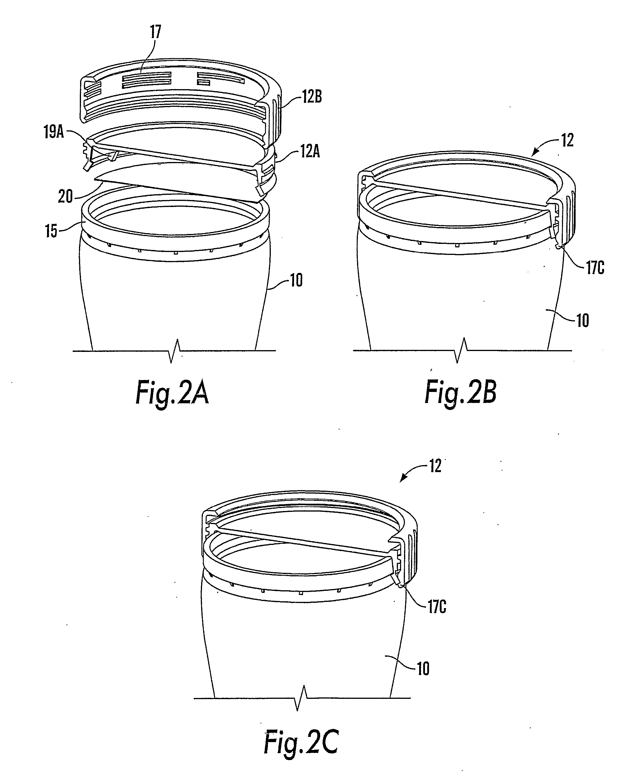
[0068]FIG. 9C shows a vertical sectional view through a fifth embodiment in which the closure means comprises a foil 150 and a collar 151 and FIGS. 9A and 9B show perspective and plan views of the collar 151.

[0069]The collar comprises a first part 151A with a gap therein and a second part 151B which can be connected to the first part 151A to join the ends of the first part 151A. The second part 151B hooks to one end of the first part 151A and has an over-centre mechanism 151C such that when moved to the closed position it remains in this position and puts the collar 151 under tension so as to clamp it more securely about the container 152 and foil 150. As shown in FIG. 9C, the collar 151 is shaped to engage under a lip 152A of container 152 and is arranged to grip the foil 50 tighter as the collar is tightened.

[0070]Part 151B is provided with a tab 151D which may be lifted like a conventional ring-pull to break the collar at one or more weak points 151E when it is desired to remove ...


PUM


Abstract

A beverage container for the storage of a carbonated drink comprising a container body (10) including an opening (11) and removable closure means (12) for closing the opening (11), the closure means comprising a foil (20) which provides a gas tight seal for the opening (11). The arrangement may be such that a tendency of forces acting on the foil (20) due to pressure within the container to separate the foil (20) from the container body (10) by peeling away therefrom is reduced e.g. by the provision of a collar (12A) to limit deflection of the foil (20) adjacent the bond therebetween and/or by the shape of the rim (15) of the container body (10), so the closure is capable of withstanding higher internal pressures than would otherwise be the case.

Description

TECHNICAL FIELD[0001]The present invention relates to beverage containers, and particularly relates to containers for supplying beverages to consumers. The invention has particular utility for the storage and supply of carbonated and other sparkling drinks, but may also be used with other types of drinks.BACKGROUND ART[0002]For many years there has been a desire among drinks suppliers and container manufacturers to provide practical wide-mouth beverage supply containers which consumers may drink from comfortably in the same manner as from a drinks glass or other drinking vessel, particularly in relation to carbonated drinks such as beers, etc. Despite the tremendous advantages that such a beverage container would provide for drinks suppliers, container manufacturers and consumers alike, no successful beverage container that fulfils these aims has yet been produced. Consequently, bottles and ring-pull cans currently remain the main practical beverage supply containers for consumers. ...

Claims


Application Information

Patent Timeline
IPC IPC(8): B65D51/20B65D45/34B65D53/04
CPCB65D45/345B65D51/20B65D53/04B65D2251/0015B65D2251/0018B65D2251/0093
Inventor FARRAR, PETER ANTONYHEIN, JOHNFRASER, ANTHONY HENRY JOSEPHMARRIOTT, MARK RUPERT JOHNDANDO, WILLIAM GEORGE
Owner DUBOIS LIMITED (GB)
Why Eureka
Try Eureka