
Defect determining device for turbo charger

Inactive Publication Date: 2006-10-12
TOYOTA JIDOSHA KK +1
View PDF13 Cites 16 Cited by
  • Summary
  • Abstract
  • Description
  • Claims
  • Application Information

AI Technical Summary

Benefits of technology

[0010] The present invention was made in view of the foregoing, and its object is to provide a defect determining device for a turbo charger that can immediately determine a defect of excessive increase in exhaust gas pressure in an exhaust passage between the internal combustion engine and the turbo charger, while preventing erroneous determination.

Problems solved by technology

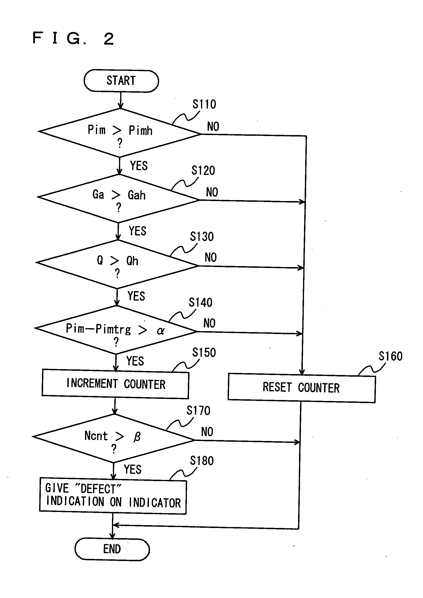
In this arrangement, the exhaust gas pressure in the exhaust passage from the internal combustion engine to the turbo charger is estimated from the state of operation of the engine, and if the estimated exhaust gas pressure is relatively low, the manner of defect determination is changed such that the determination of any defect is not readily made even when the actual boost pressure exceeds the target boost pressure.

Method used


Image

  • Defect determining device for turbo charger
  • Defect determining device for turbo charger
  • Defect determining device for turbo charger

Examples


Embodiment Construction

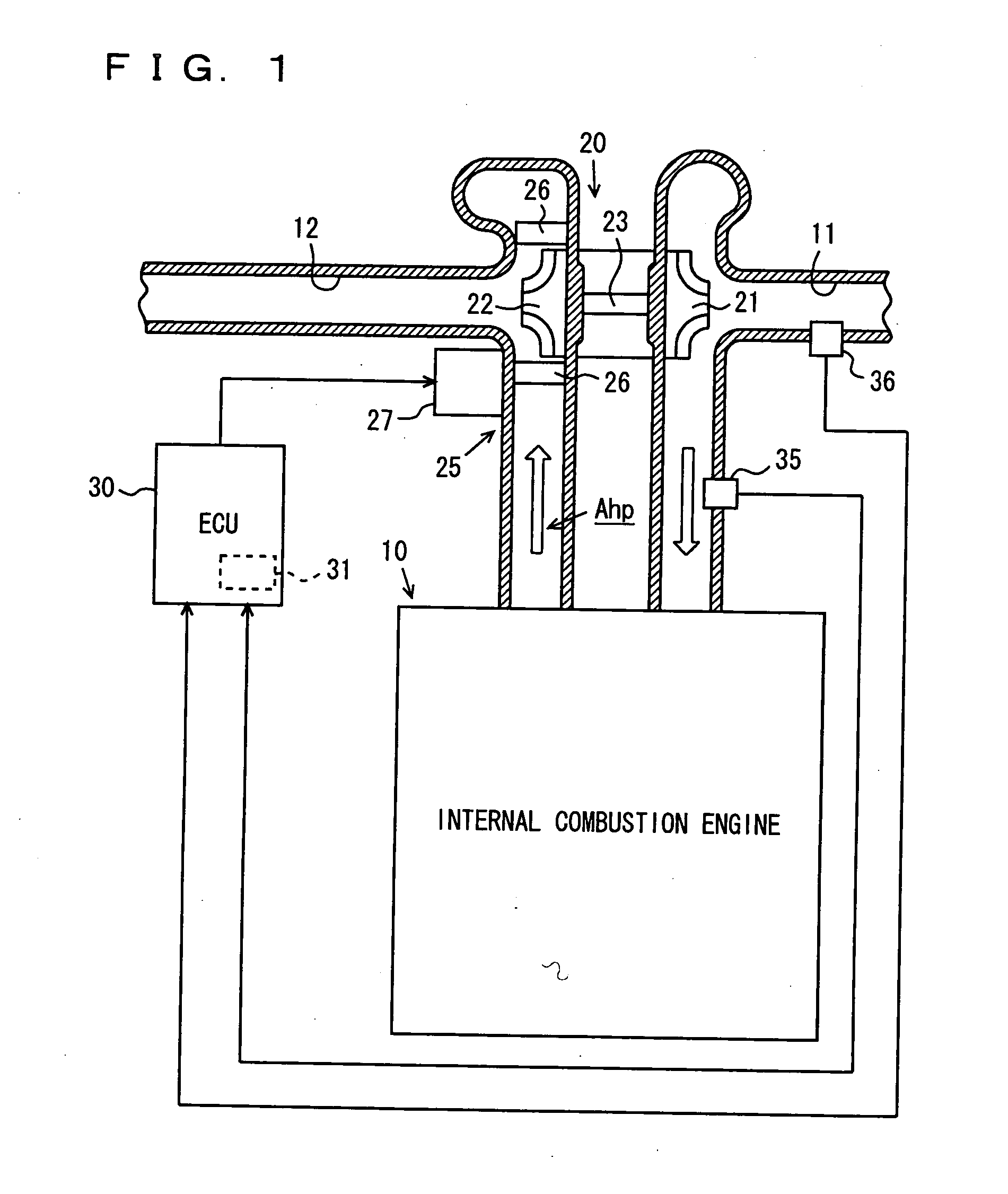
[0035] In the following, an embodiment of the present invention applied to a defect determining device for a turbo charger in a diesel engine for a vehicle will be described with reference to FIGS. 1 to 5.

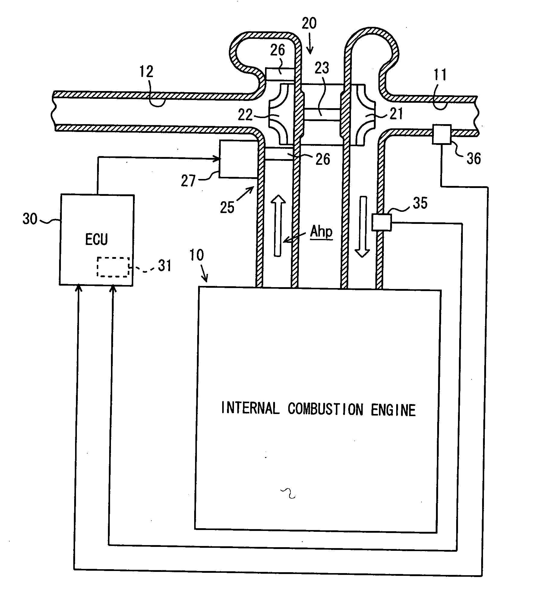
[0036]FIG. 1 shows a diesel engine to which a turbo charger is mounted, and intake / exhaust system configurations thereof As can be seen from the figure, to the diesel engine (hereinafter simply referred to as an engine) 10, an intake passage 11 and an exhaust passage 12 are connected. Intake air introduced through intake passage 11 to a combustion chamber, not shown, of engine 10 is used for combustion of fuel in the chamber, and a gas generated by combustion goes out as an exhaust gas to exhaust passage 12.

[0037] In the middle of intake passage 11 and exhaust passage 12, a turbo charger 20 is provided, for super-charging intake air to the engine combustion chamber utilizing pressure of the exhaust gas (exhaust gas pressure). Turbo charger 20 includes a compressor wheel 21 for pr...


PUM


Abstract

An ECU (electronic control unit) determines whether a turbo charger is defective or not based on degree of deviation between a target boost pressure Pimtrg and an actual boost pressure Pim of the turbo charger. Further, ECU estimates exhaust gas pressure of an exhaust passage from the internal combustion engine to the turbo charger based on a state of engine operation, and determines whether or not the estimated exhaust gas pressure is relatively low. When it is determined that the exhaust gas pressure is relatively low, the manner of defect determination is changed such that the determination of defect is not readily made.

Description

[0001] This nonprovisional application is based on Japanese Patent Application No. 2005-112831 filed with the Japan Patent Office on Apr. 8, 2005, the entire contents of which are hereby incorporated by reference. BACKGROUND OF THE INVENTION [0002] 1. Field of the Invention [0003] The present invention relates to a defect determining device for determining a defect of a turbo charger having a boost pressure changing mechanism, which allows change in boost pressure in accordance with the state of operation of an internal combustion engine. [0004] 2. Description of the Background Art [0005] A turbo charger utilizing exhaust gas pressure has been widely known as a super-charging system for forced feeding of intake air to the combustion chamber of the internal combustion engine, to attain higher charging efficiency. In the turbo charger, it is desirable to appropriately adjust the boost pressure in accordance with the state of operation of the internal combustion engine. To meet this de...

Claims


Application Information

Patent Timeline
IPC IPC(8): F02B33/44
CPCF02B37/22F02B39/16F02D41/0007Y02T10/144F02D41/221Y02T10/40F02D41/145Y02T10/12
Inventor KISHIMOTO, GAKUTOYOSHIMA, MINORUTANIZAWA, SEIGAKU
Owner TOYOTA JIDOSHA KK
Learn More