Wheel position detection device and tire-pressure detection system equipped with same

Inactive Publication Date: 2018-05-17
DENSO CORP
View PDF5 Cites 12 Cited by
  • Summary
  • Abstract
  • Description
  • Claims
  • Application Information

AI Technical Summary

Benefits of technology

[0017]In the tire pressure detection system described above, the determination of the identification information on the spare wheel can be prevented from being performed when the identification information on the transmitter of the spare wheel in the host vehicle is not registered as the candidate due to a full c

Problems solved by technology

However, according to the conventional methods of registering the ID information, the ID information on the receivers attached to both of traveling wheels and a spare wheel (auxiliary wheel) in the host vehicle cannot be registered while specifying the wheel position.
In addition, in the method paying attention to the reception frequency, since the reception frequency is the same between the tr

Method used


Image

  • Wheel position detection device and tire-pressure detection system equipped with same
  • Wheel position detection device and tire-pressure detection system equipped with same
  • Wheel position detection device and tire-pressure detection system equipped with same

Examples


first embodiment

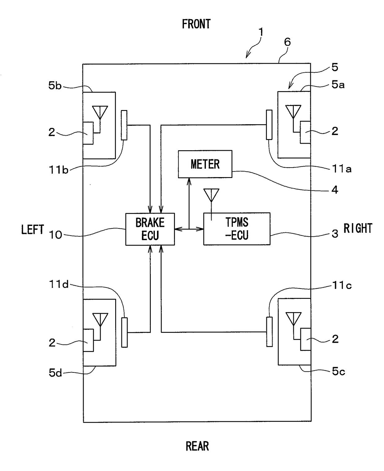
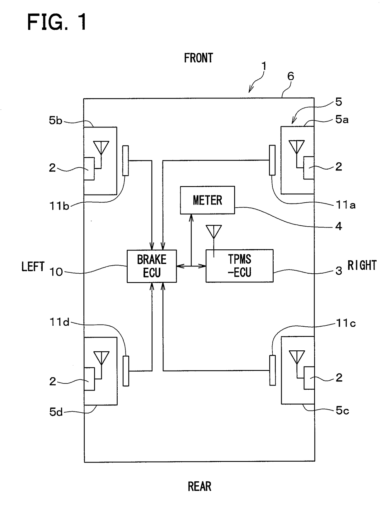
[0038]A first embodiment of the present disclosure will be described with reference to the drawings. FIG. 1 is a diagram illustrating an overall configuration of a TPMS to which a wheel position detection device is applied according to a first embodiment of the present disclosure. An upward direction on paper of FIG. 1 coincides with a front of a vehicle 1 and a downward direction on the page coincides with a rear of the vehicle 1. The TPMS according to the present embodiment will be described with reference to the figure.

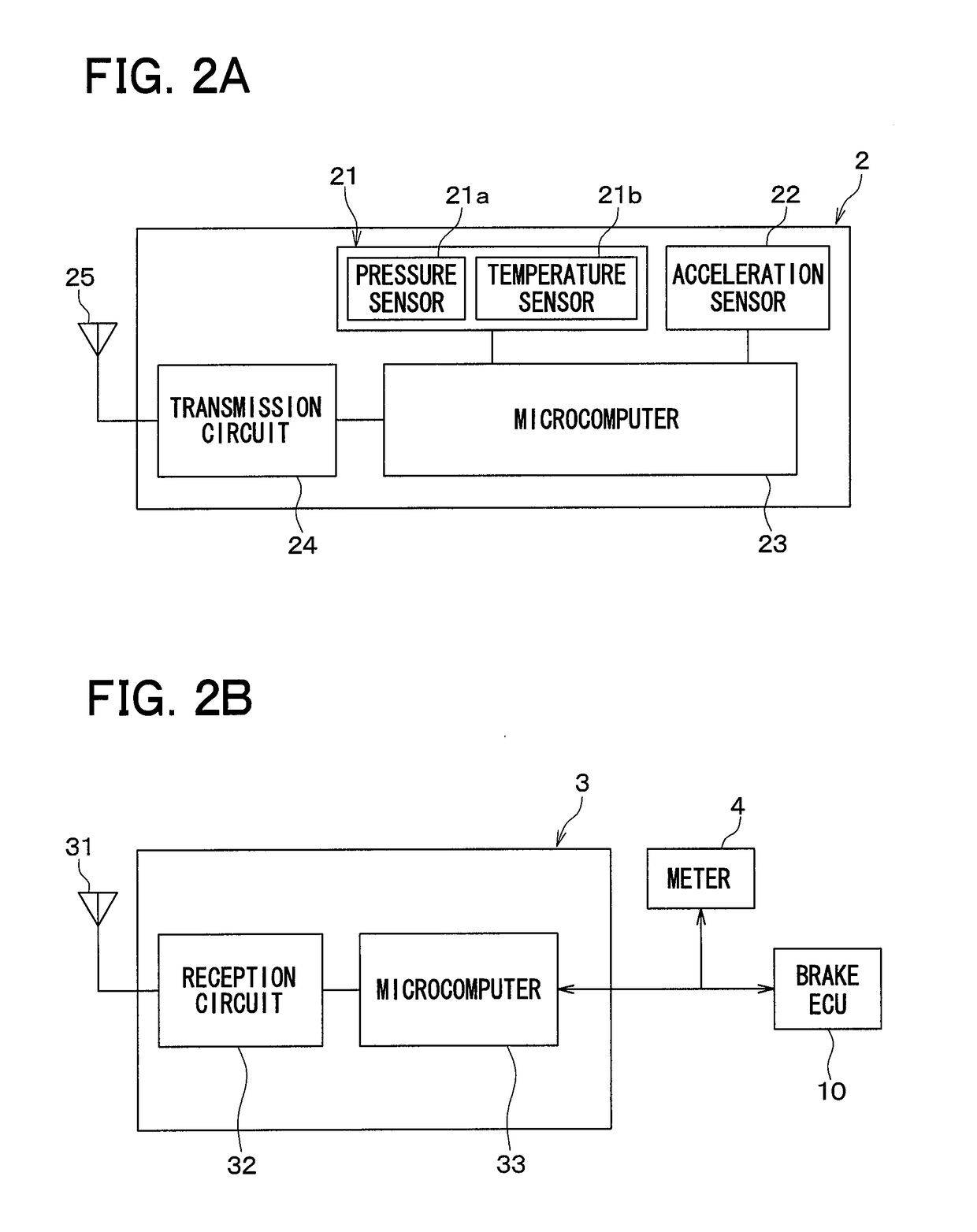
[0039]As illustrated in FIG. 1, the TPMS is provided in the vehicle 1, and is configured to include transmitters 2, an ECU for the TPMS (hereinafter referred to as TPMS-ECU) 3 serving as a receiver, and a meter 4. The wheel position detection device uses the transmitters 2 and the TPMS-ECU 3 provided in the TPMS, and also acquires gear information obtained from detection signals of wheel speed sensors 11a to 11d provided corresponding to respective wheels 5 (5a to ...

second embodiment

[0136]A second embodiment of the present disclosure will be described. In the present embodiment, the process to be executed in Step 260 of FIG. 8 described in the first embodiment is changed, and the other processes are identical with those in the first embodiment. Therefore, only parts different from those in the first embodiment will be described.

[0137]As illustrated in FIG. 12, in the present embodiment, a spare wheel registration process is executed as in the first embodiment. However, Step 260 is replaced with the process of Step 260a.

[0138]More specifically, in Step 260a, it is determined whether identification of the ID information on the traveling wheels 5a to 5d has been completed, or not. The identification of the ID information of the traveling wheels 5a to 5d is not completed unless there is the travel history after shifting to the registration mode. For that reason, the completion of identification of the ID information of the traveling wheels 5a to 5d is one of the r...


PUM


Abstract

A wheel position detection device includes: a transmitter in each wheel of a vehicle having a first control unit for transmitting a frame with ID and an acceleration sensor; and a receiver on a vehicle body, including a second control unit for registering the ID in association with the wheel. The first control unit detects a wheel speed, and stores data of the acceleration sensor in the frame. The second control unit includes: a first determination device that determines a condition that the acceleration sensor is not in an on-state; a candidate registration device that registers a candidate of the ID of a spare wheel when the condition is satisfied; a second determination device that determines a travel history of the vehicle; and a registration device that identifies the ID of the spare wheel when the travel history is present, and registers the ID in association with the spare wheel.

Description

CROSS REFERENCE TO RELATED APPLICATION[0001]This application is based on Japanese Patent Application No. 2015-114240 filed on Jun. 4, 2015, the disclosure of which is incorporated herein by reference.TECHNICAL FIELD[0002]The present disclosure relates to a wheel position detection device that automatically detects where a target wheel is mounted in a vehicle and a direct type tire pressure detection system equipped with the same.BACKGROUND ART[0003]Up to now, as one of tire pressure detection systems (hereinafter referred to as TPMS: tire pressure monitoring system), there is a direct type tire pressure detection system. In the TPMS of that type, a transmitter equipped with a sensor such as a pressure sensor is attached directly to a wheel side to which a tire is attached. An antenna and a receiver are provided on a vehicle body side. When a detection signal from the sensor is transmitted from the transmitter, the detection signal is received by the receiver through an antenna to de...

Claims


Application Information

Patent Timeline
IPC IPC(8): B60C23/04
CPCB60C23/0416B60C23/0488B60C23/0489G01P15/00
Inventor OKADA, NORIAKIFUKUDA, MASAHIRO
Owner DENSO CORP
Why Eureka
Try Eureka