Clothes hanger

a clothes hanger and clothes technology, applied in the field of clothes hangers, can solve the problems of only suitable conventional clothes hangers and does not meet the needs of users, and achieve the effects of saving the required space for hanging, convenient operation, and increasing practicability and convenience of the present invention

Inactive Publication Date: 2006-10-12
WELLITE ENTERPRISE
View PDF13 Cites 25 Cited by
  • Summary
  • Abstract
  • Description
  • Claims
  • Application Information

AI Technical Summary

Benefits of technology

[0003] It is a main object of the present invention to provide an improved clothes hanger having hanging fins pivotally mounted on the lower lateral surfaces of a base, wherein the hanging fins are detachably held by the buckle means, which are mounted on the upper lateral surfaces of the base, such that the hanging fins can be put to use in both folded and unfolded forms. Besides, it is convenient to operate the present invention so the practicability and convenience of the present invention are increased.
[0004] It is another object of the present invention to provide an improved clothes hanger, wherein the hanging fins are detachably held by the buckle means mounted on the upper lateral surfaces of the base so that the folded hanging fins can further save the required space for hanging the clothes and increase the practicability of the clothes hanger.
[0005] In order to achieve the aforementioned object, the present invention discloses an improved clothes hanger. The clothes hanger comprises a base and two hanging fins. The base comprises two buckle means mounted on the upper lateral surfaces of the base and a hook mounted on a top surface of the base. The hanging fins are movably mounted on the lower lateral surfaces of the base for detachably hooking the buckle means. A plurality of through holes are formed on the hanging fins at intervals so that the hanging fins can be put to use in both folded and unfolded forms and the required space for hanging the clothes can be saved by the folded hanging fins.

Problems solved by technology

However, this conventional type clothes hanger is only suitable for one article of clothing.
Accordingly, the conventional type clothes hanger does not fill the need of the user when it is put into actual use.

Method used


Image

  • Clothes hanger
  • Clothes hanger
  • Clothes hanger

Examples


Embodiment Construction

[0013] The preferred embodiment of the present invention will now be described in detail with reference to the drawings.

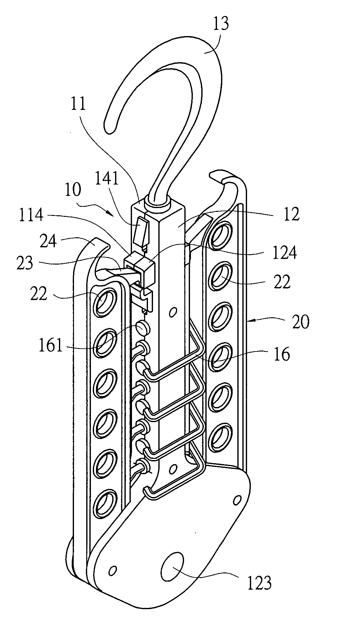
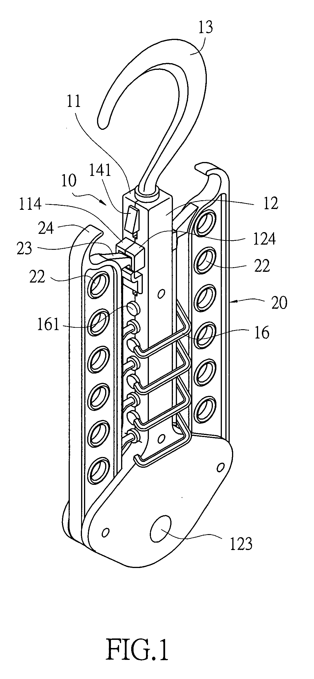
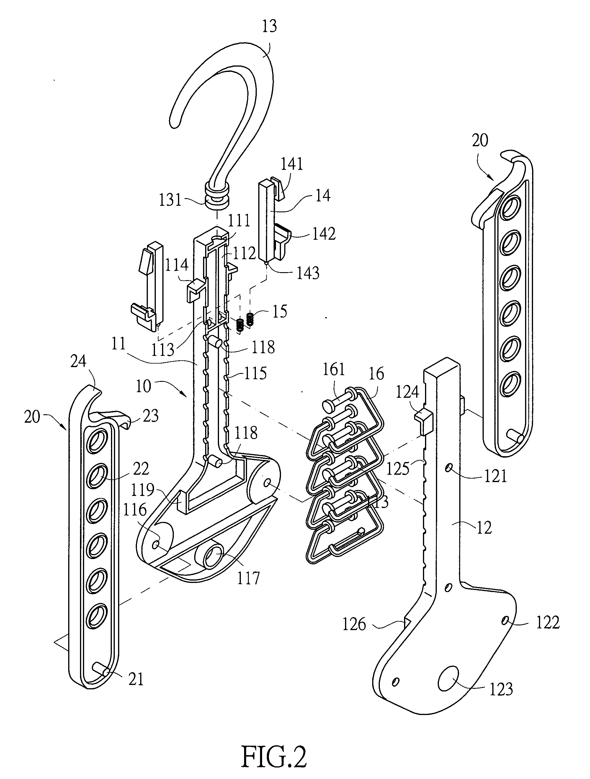
[0014] Referring to FIG. 1 through FIG. 4, an improved structure of a clothes hanger of the present invention is shown. The clothes hanger comprises a base 10 and two hanging fins 20. The base 10 is composed of two coupled housings 11, 12, wherein two buckle means 14 are mounted on the upper lateral surfaces of the base 10, and a hook 13 is mounted on a top surface of the base 10. Two sliding grooves 112 are formed on the upper portions of the housings 11, 12, and two elastic means 15 are respectively mounted on the bottom surfaces of the sliding grooves 112. The buckle means 14 are leant against the elastic means 15 and movably mounted in the sliding grooves 112, respectively. A protrudent part 141 is mounted on the upper exterior portion of each buckle means 14. Besides, an outwardly bended hook part 142 is formed below each buckle means 14. A pillar 143 is form...


PUM


Abstract

A clothes hanger comprises a base and hanging fins. The base comprises buckle means mounted on upper lateral surfaces of the base and a hook mounted on a top surface of the base. The hanging fins are movably mounted on lower lateral surfaces of the base for detachably hooking the buckle means. A plurality of through holes are formed on the hanging fins at intervals so that the clothes hanger can be put to use in both folded and unfolded forms and the required space for hanging the clothes can be further saved by the folded hanging fins.

Description

FIELD OF THE INVENTION [0001] The present invention relates to an improved clothes hanger and more particularly to a clothes hanger or a similar structure having hanging fins, which are pivotally mounted on the lower lateral surfaces of a base, wherein the hanging fins are detachably held by buckle means, which are mounted on the upper lateral surfaces of the base, such that the hanging fins can be put to use in both folded and unfolded forms, and the required space for hanging the clothes can be saved by the hanging fins in the folded form. Accordingly, the clothes hanger of the present invention is suitable for dwelling houses and all kind of marketplaces. BACKGROUND OF THE INVENTION [0002] The conventional clothes hanger generally includes a bended part, which is bended into a hook and a triangular frame (not shown). An article of clothing is hung on the triangular frame and the hook is hung on a rod. However, this conventional type clothes hanger is only suitable for one article...

Claims


Application Information

Patent Timeline
IPC IPC(8): A41D27/22
CPCA47G25/743A47G25/0685
Inventor HSU, MING-YU
Owner WELLITE ENTERPRISE
Why Eureka
Try Eureka