
Mechanism for adjusting the inclination of a motor vehicle seat

a technology for adjusting the inclination of the motor vehicle seat, which is applied in the direction of vehicle seats, movable seats, vehicle arrangements, etc., can solve the problems that the adjustment mechanism cannot be used in satisfactory manner by the occupants of the vehicle, and it is difficult to reduce the risk sufficiently to comply, so as to avoid the risk of jamming and achieve satisfactory

Active Publication Date: 2006-10-12
FAURECIA
View PDF12 Cites 12 Cited by
  • Summary
  • Abstract
  • Description
  • Claims
  • Application Information

AI Technical Summary

Benefits of technology

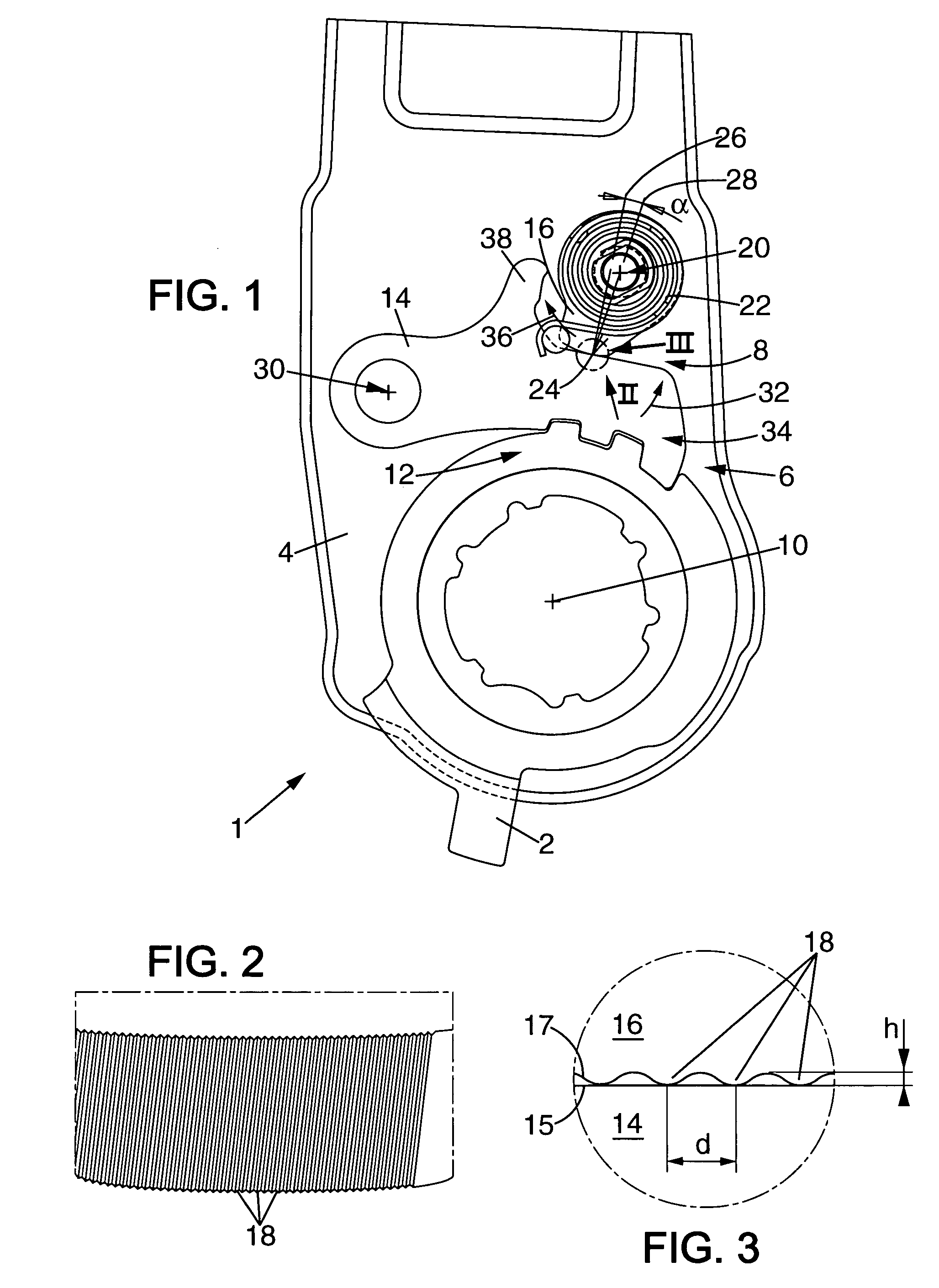
[0009] Thus, it is possible to adjust the mechanism to avoid the cam jamming in the active position while the vehicle is being used normally, while also preventing the locking device from unlocking. In the event of extreme stress, the teeth penetrate into the facing bearing surface so as to anchor therein.
[0011] Thus, the bearing surface of the cam can come tangentially into contact with the bearing surface of the second locking element, thereby avoiding any slack therebetween.
[0013] Thus, the penetration of the teeth into the facing smooth surface is improved.
[0017] Teeth are thus obtained that are sufficiently tall to anchor effectively and that are not too slender so that they do not break. In addition, they are reasonably close together so that a plurality of them become anchored and so that the material of the facing bearing surface can engage between them effectively.
[0025] Thus, satisfactory effectiveness is obtained for the anchoring between the cam and the second locking element in the event of extreme stress, while also avoiding the risk of jamming during normal operation.

Problems solved by technology

However, it is very difficult to reduce that risk sufficiently to comply with the specifications of automobile makers without risking the cam jamming in the active position.
The adjustment mechanism cannot therefore be used in satisfactory manner by the occupants of the vehicle because said occupants are obliged to exert a large amount of force for unlocking the mechanism using control means provided for this purpose and including the cam.

Method used


Image

  • Mechanism for adjusting the inclination of a motor vehicle seat
  • Mechanism for adjusting the inclination of a motor vehicle seat
  • Mechanism for adjusting the inclination of a motor vehicle seat

Examples


Embodiment Construction

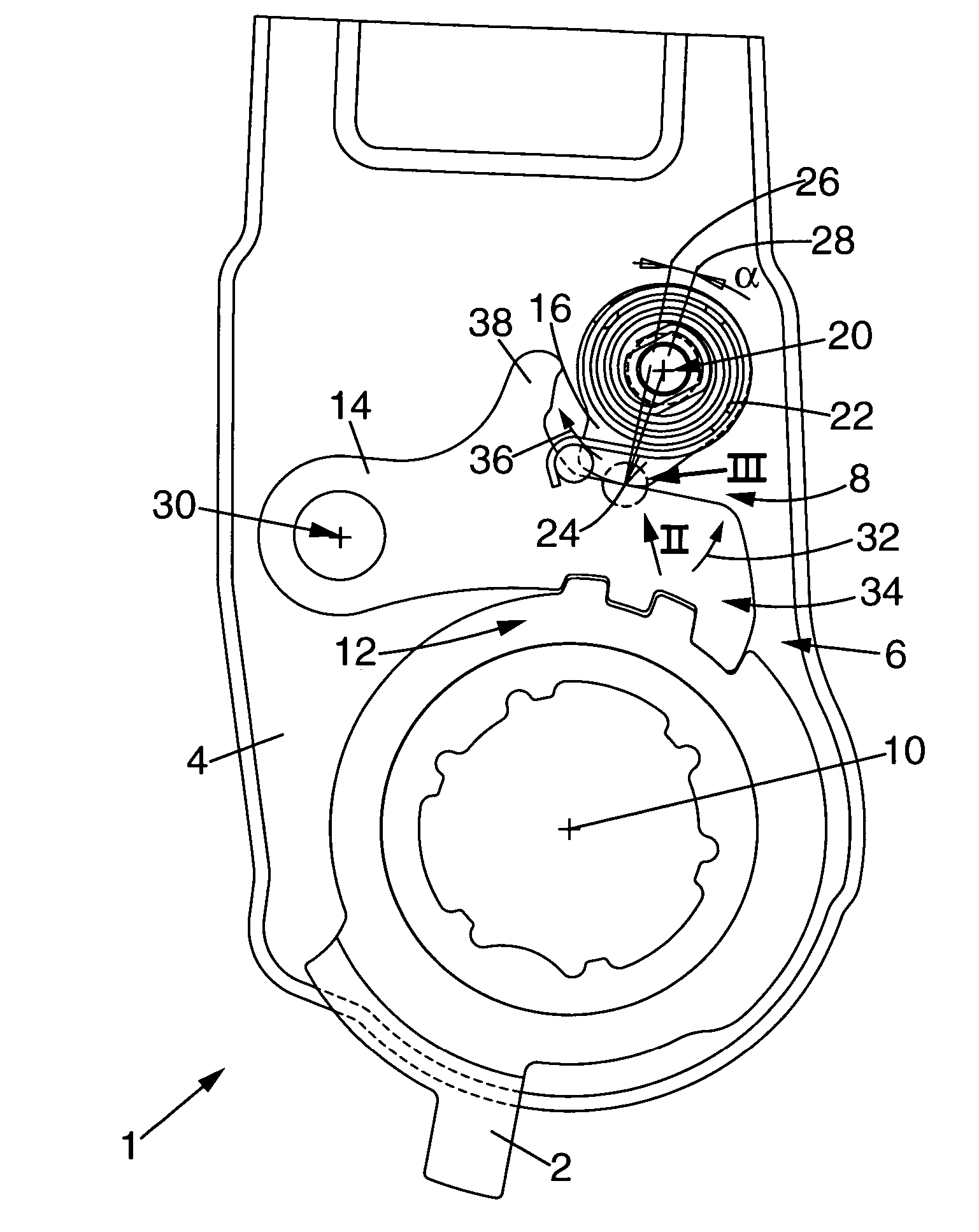
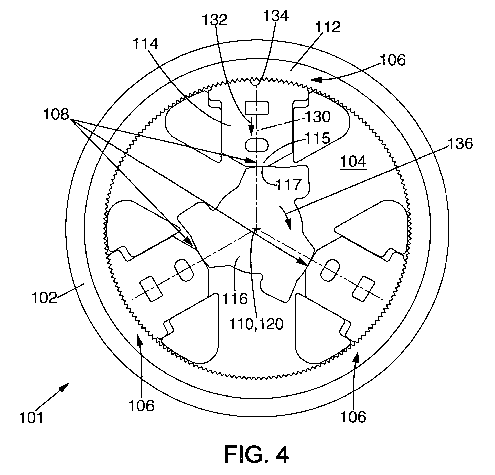
[0031] FIGS. 1 to 3 show a mechanism 1 for adjusting the inclination of a motor vehicle seat. The mechanism 1 essentially comprises a stationary cheek plate 2, a moving cheek plate 4 mounted to pivot relative to the stationary cheek plate 2 about an inclination axis 10, a locking device 6 for preventing the moving cheek plate 4 from pivoting relative to the stationary cheek plate 2, and a non-reverse device 8.

[0032] The stationary cheek plate 2 is designed to be fastened to the seat proper. The moving cheek plate 4 is designed to be fastened to the seat back.

[0033] The locking device 6 essentially comprises a crenellated portion 12 provided on the stationary cheek plate 2 and a catch 14 mounted to pivot relative to the moving cheek plate 4 about a pivot axis 30 parallel to the inclination axis 10. The catch 14 is provided with a crenellated portion 34 that is complementary to the crenellated portion 12 of the stationary cheek plate 2.

[0034] When the locking device 6 is in an acti...


PUM


Abstract

A mechanism for adjusting the inclination of a motor vehicle seat, said mechanism comprising: a first cheek plate and a second cheek plate, said second cheek plate being mounted to pivot on the first cheek plate; a locking device for preventing the first cheek plate from pivoting relative to the second cheek plate, said locking device comprising a first locking element coupled to the first cheek plate, and a second locking element mounted to move on the second cheek plate between an active position and an inactive position; a non-reverse device comprising a cam mounted to pivot between an active position in which said cam comes into contact with the second locking element, and an inactive position; The cam and / or the second locking element is / are provided with teeth.

Description

[0001] The invention relates to a mechanism for adjusting the inclination of a motor vehicle seat. [0002] It aims more particularly to prevent the back of the seat from coming out of adjustment in unwanted manner when high stress is exerted on the seat back. BACKGROUND OF THE INVENTION [0003] A mechanism is already known that comprises in usual manner: [0004] a first cheek plate and a second cheek plate designed to be fastened one to a seat back and the other to a seat proper, said second cheek plate being mounted to pivot on the first cheek plate about a first pivot axis; [0005] a locking device for preventing the first cheek plate from pivoting relative to the second cheek plate, said locking device comprising a first locking element coupled to the first cheek plate, and a second locking element mounted to move on the second cheek plate between an active position in which it co-operates with the first locking element to prevent the second cheek plate from pivoting relative to the ...

Claims


Application Information

Patent Timeline
Patent Type & Authority Applications(United States)
IPC IPC(8): B60N2/02
CPCB60N2/235B60N2/2356B60N2/2352B60N2/236
Inventor LECONTE, SEBASTIEN
Owner FAURECIA
Learn More