
In-vehicle complex biometric authentication system and operation method thereof

a biometric authentication and vehicle technology, applied in the direction of pedestrian/occupant safety arrangement, anti-theft devices, instruments, etc., can solve the problems of information disclosure, vehicle theft problem, lax prevention of vehicle theft, etc., to reduce the additional time for driver authentication, increase security, and contribute to user convenience

Active Publication Date: 2021-10-28
LG ELECTRONICS INC
View PDF0 Cites 2 Cited by
  • Summary
  • Abstract
  • Description
  • Claims
  • Application Information

AI Technical Summary

Benefits of technology

The patent is about a new technology that allows for more efficient and accurate positioning of a device in a virtual or real-world environment. This can be useful in a variety of applications, such as in augmented reality or virtual reality. The technology uses a special technique called time-domain electromagnetic tomography to create a map of the device's position in real-time. This allows for smoother and more precise navigation through virtual or real spaces, making it easier to reach and interact with objects.

Problems solved by technology

However, the biometric authentication uses the user's unique biometric information, which can lead to information disclosure problems.
On the other hand, when the driver of the vehicle has performed biometric authentication and temporarily got off the vehicle for parking, refueling, etc., a vehicle theft problem may occur.
In such cases, if authentication is set to be maintained continuously for the convenience of the driver, the prevention of vehicle theft may be lax.
On the other hand, if biometric authentication is required repeatedly by emphasizing the aspects of prevention of vehicle theft, the discomfort of the driver may be greatly increased, thereby reducing the efficiency of use.

Method used


Image

  • In-vehicle complex biometric authentication system and operation method thereof
  • In-vehicle complex biometric authentication system and operation method thereof
  • In-vehicle complex biometric authentication system and operation method thereof

Examples


Embodiment Construction

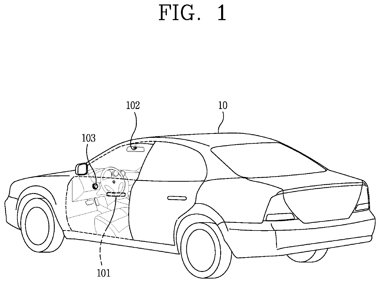
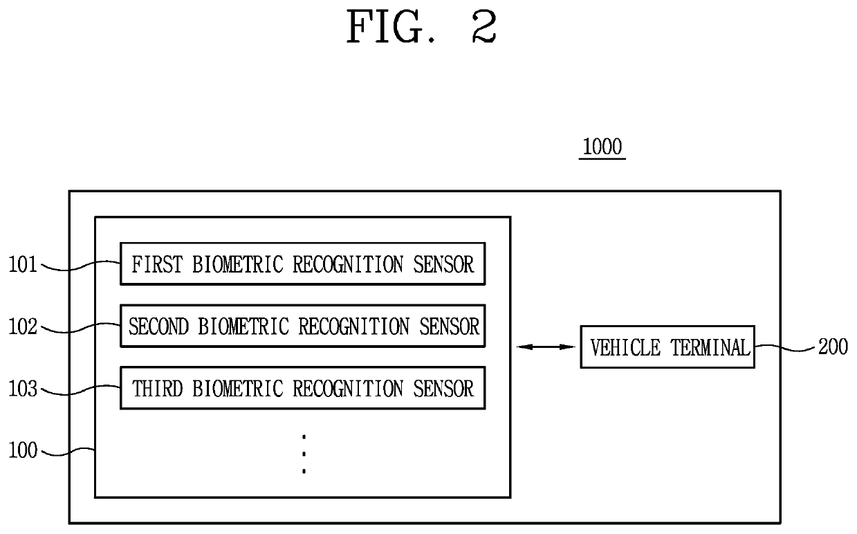
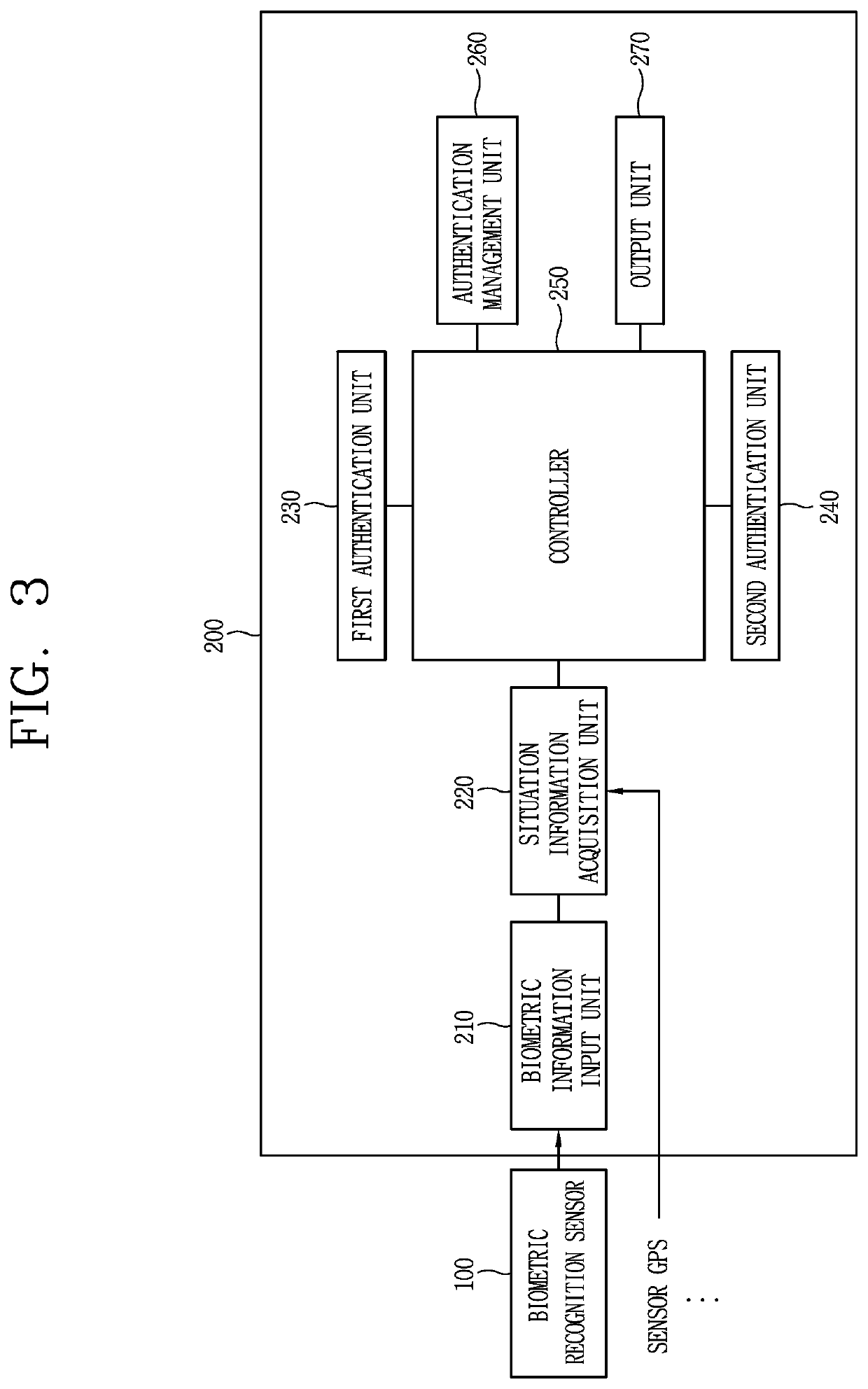
[0035]Description will now be given in detail according to exemplary embodiments disclosed herein, with reference to the accompanying drawings. For the sake of brief description with reference to the drawings, the same or equivalent components may be provided with the same or similar reference numbers, and description thereof will not be repeated. In general, a suffix such as “module” and “unit” may be used to refer to elements or components. Use of such a suffix herein is merely intended to facilitate description of the specification, and the suffix itself is not intended to give any special meaning or function. In describing the present disclosure, if a detailed explanation for a related known function or construction is considered to unnecessarily divert the gist of the present disclosure, such explanation has been omitted but would be understood by those skilled in the art. The accompanying drawings are used to help easily understand the technical idea of the present disclosure ...


PUM


Abstract

An in-vehicle complex biometric authentication system includes: a sensor to sense a driver's boarding of a vehicle; a controller to perform driver authentication based on biometric information sensed by multiple biometric sensors when driver's boarding in a vehicle is detected by the sensor, and to collect driver's identification information and driving habit information during operation of a vehicle when the driver authentication is succeeded; and a memory to store the identification information and driving habit information as implicit authentication information, wherein the controller further detects situation recognition information related to the implicit authentication information, after the driver authentication is succeeded, and determines whether to perform additional authentications based on the matching result of the detected situation recognition information with the implicit authentication information. According the present invention, the system can provide a biometric authentication system to which the IOT is applied.

Description

TECHNICAL FIELD[0001]The present disclosure relates to an in-vehicle complex biometric authentication system and an operation method thereof, and more particularly, to an in-vehicle complex biometric authentication system and an operation method thereof, capable of preventing vehicle theft using a complex biometric authentication.BACKGROUND ART[0002]For the convenience of users of vehicles, various types of sensors and electronic devices are being installed. In particular, research on the Advanced Driver Assistance System (ADAS) of vehicles is being carried out actively for the convenience of users' driving. Furthermore, the development of autonomous vehicles is actively ongoing.[0003]In addition, considering both the convenience and safety of users using vehicles, researches and applications on the driver authentication of the biometric authentication are actively ongoing.[0004]The biometric authentication is a way to authenticate users based on behavioral results using a unique fo...

Claims


Application Information

Patent Timeline
Patent Type & Authority Applications(United States)
IPC IPC(8): B60R25/25B60R25/34B60W40/08G06K9/00
CPCB60R25/25B60R25/34B60W40/08B60W2556/10G06K9/00926B60W2040/0809G06K9/00892B60W2040/0872B60W2040/0881B60W2040/089B60W2540/30B60W50/14G06V40/172G06V40/1365G06V20/59B60R21/01542B60R21/01566G06V40/50G06V40/70
Inventor KIM, KOKEUNKIM, JIHYESIM, SOOYOUNGKIM, BEOMOHKIM, SUNGJIN
Owner LG ELECTRONICS INC
Learn More