Injector device with force lock-out and injection rate limiting mechanisms

a technology of injection rate and injection device, which is applied in the direction of injection syringes, intravenous devices, automatic syringes, etc., can solve the problems that the typical injection system used for subcutaneous delivery is not believed to be optimal for the general population of self-injectors

Active Publication Date: 2006-10-12
BECTON DICKINSON & CO
View PDF83 Cites 154 Cited by
  • Summary
  • Abstract
  • Description
  • Claims
  • Application Information

AI Technical Summary

Benefits of technology

[0009] An aspect of one implementation of the present invention is to provide an injection device having a lock-out mechanism, wherein the plunger/injection mechanism of the injection device is inoperable unless a lock-out release force is applied to the proximal end

Problems solved by technology

Current typical pen injection systems used for subcutaneous delivery are not believed to be optimal for use by the general population of self-injectors because of, inter alia, the high backpressures associated with injecting fluid into the intradermal layers of the

Method used


Image

  • Injector device with force lock-out and injection rate limiting mechanisms
  • Injector device with force lock-out and injection rate limiting mechanisms
  • Injector device with force lock-out and injection rate limiting mechanisms

Examples


Embodiment Construction

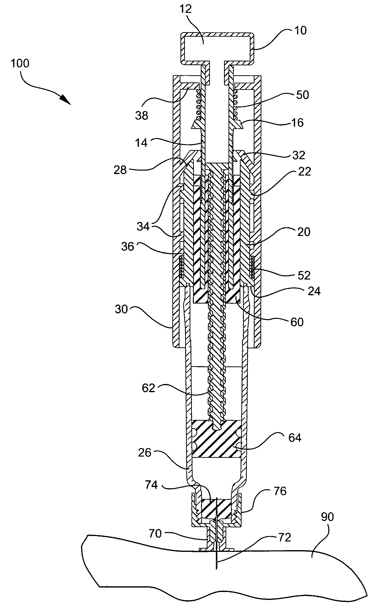
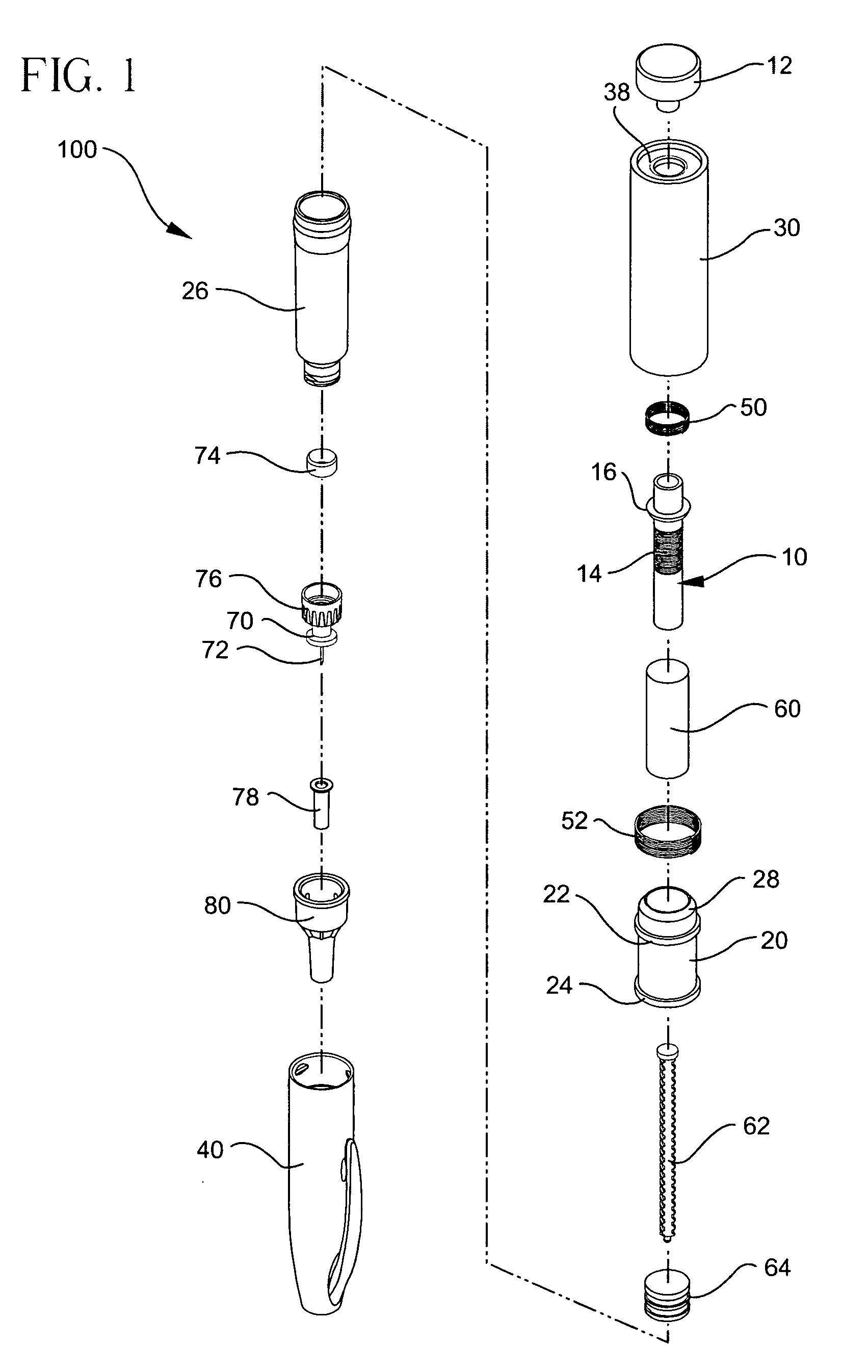
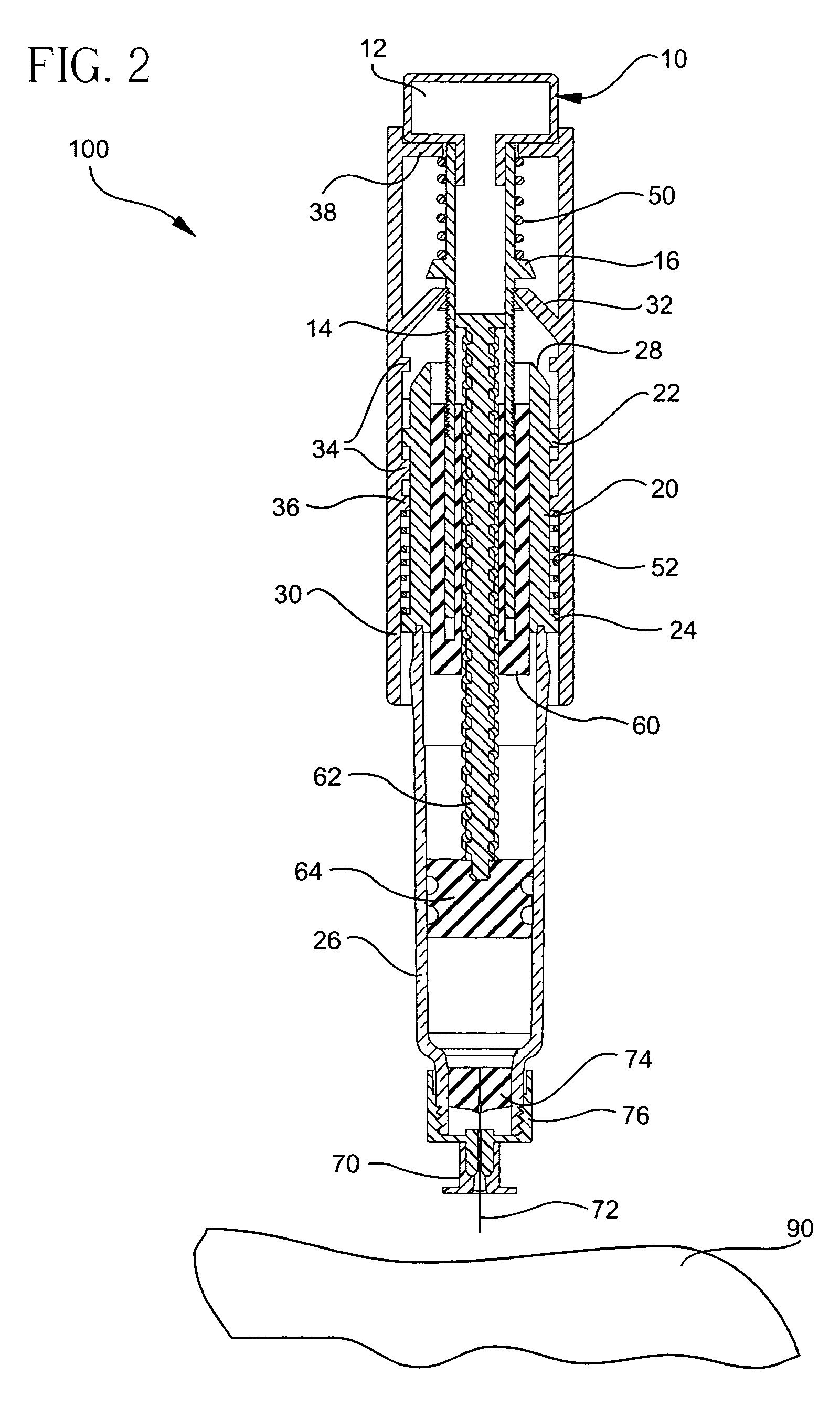
[0029] In FIG. 1, an exemplary embodiment of the present invention is shown. FIG. 1 is an exploded view illustrating an example of a device assembly according to an embodiment of the present invention, and FIGS. 2 through 5 are cross-sectional side views of the device of FIG. 1 in sequential operating positions. Specifically, FIG. 2 illustrates the device in a pre-injection / dialed-in position, FIG. 3 illustrates the device in a pre-injection / dialed-out position, FIGS. 4A and 4B illustrate the device in an in-use position, and FIGS. 5A and 5B illustrate the device in a post use position. Each position is described in greater detail below. FIGS. 6 and 7 are perspective views illustrating an assembled and uncapped device, and an assembled and capped device, respectively, according to an embodiment of the present invention.

[0030] In the embodiment of the present invention shown in FIGS. 1 through 5, an injection device, exemplified by a pen injector device 100, comprises a plunger 10, ...


PUM


Abstract

An injectable substance delivery device comprising a pen device body, a cartridge, a plunger, a drive mechanism, and at least one of a lock-out mechanism and a rate-limiting mechanism. The lock-out mechanism is provided through a ratchet engagement between the body and the plunger to restrict plunger movement and to ensure that the required needle puncture depth is realized prior to injection by locking out the injection mechanism from advancing until a specified force is applied to the skin. A rate-limiting mechanism is also provided through a user compressed plunger drive spring to ensure that a specific rate of injection is realized during the injection of a medicament.

Description

CROSS-REFERENCE TO RELATED APPLICATIONS [0001] This application contains subject matter related to that disclosed in a U.S. patent application of Pettis et al., entitled “Microneedle-Based Pen Device For Drug Delivery And Method For Using Same”, Ser. No. 10 / 238,958, filed on Sep. 11, 2002, and in a U.S. patent application of Marsh et al., entitled “Injection Device With Secondary Reservoir”, Attorney Docket No. P-6434 (47686), filed concurrently herewith, the entire content of each application being incorporated herein by reference.FIELD OF THE INVENTION [0002] The present invention relates generally to substance delivery devices. Specifically, one implementation of the invention relates to an injection device and method that incorporates a lock-out mechanism to prevent or minimize leakage of medicament during and after delivery by ensuring proper contact with the skin surface prior to activation. BACKGROUND OF THE INVENTION [0003] Currently, several injection systems are commercial...

Claims


Application Information

Patent Timeline
IPC IPC(8): A61M5/315
CPCA61M5/20A61M5/28A61M5/315A61M5/31551A61M5/31561A61M2005/2013A61M5/3158A61M5/31593A61M5/3202A61M5/46A61M5/31571
Inventor LOVELL, JOHNWEST, ROBERT E.CHELAK, TODD M.EASTERBROOK, WILLIAMFOLLMAN, MARK A.BROWKA, EDWARD P.
Owner BECTON DICKINSON & CO
Why Eureka
Try Eureka