Sheath assembly for spinal stabilization device

Inactive Publication Date: 2006-10-12
APPLIED SPINE TECH
View PDF44 Cites 201 Cited by
  • Summary
  • Abstract
  • Description
  • Claims
  • Application Information

AI Technical Summary

Benefits of technology

[0014] Spinal stabilization systems and/or other surgical implants that include a cover and/or sheath structure are desirable in that they provide protection to inner force-imparting component(s), e.g., one or more springs, while exhibiting clinically acceptable interaction with surrounding a

Problems solved by technology

Low back pain is one of the most expensive diseases afflicting industrialized societies.
While fusion is effective about seventy percent of the time, there are consequences even to these successful procedures, including a reduced range of motion and an increased load transfer to adjacent levels of the spine, which may accelerate degeneration at those le

Method used


Image

  • Sheath assembly for spinal stabilization device
  • Sheath assembly for spinal stabilization device
  • Sheath assembly for spinal stabilization device

Examples


Embodiment Construction

)

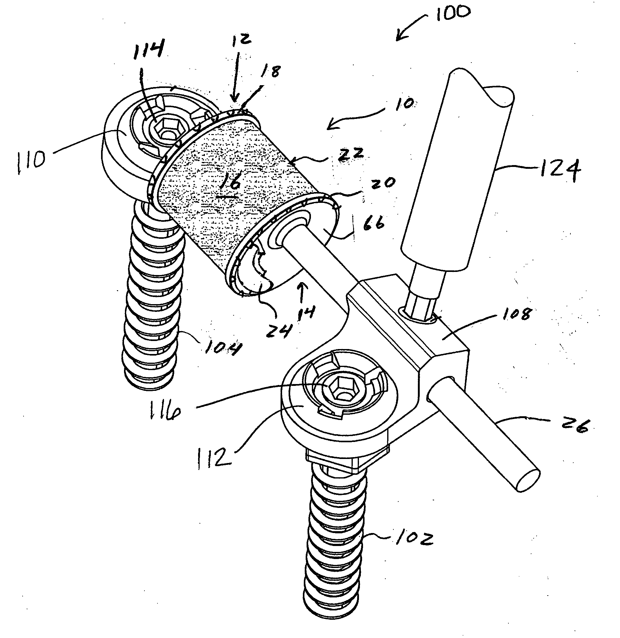
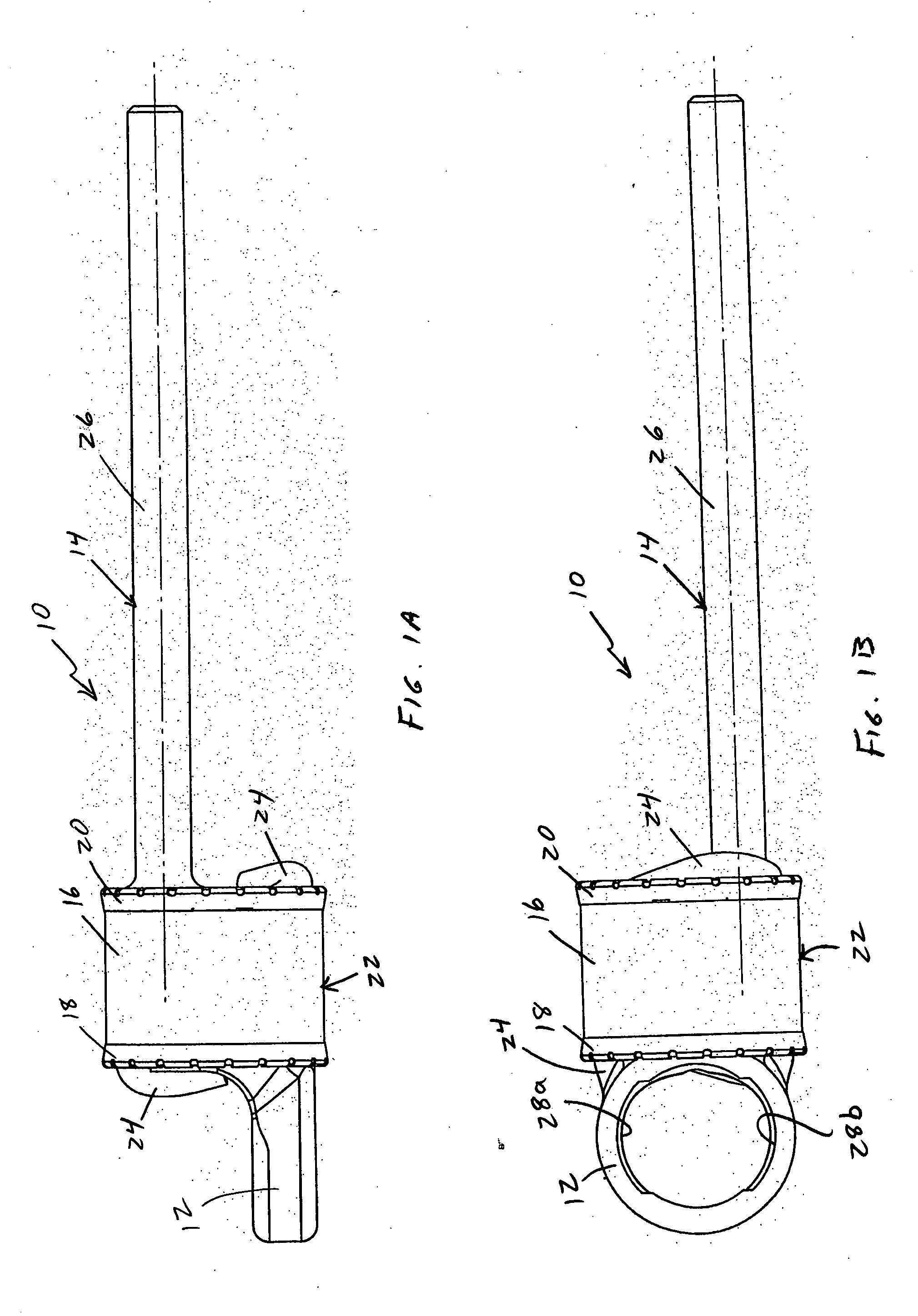
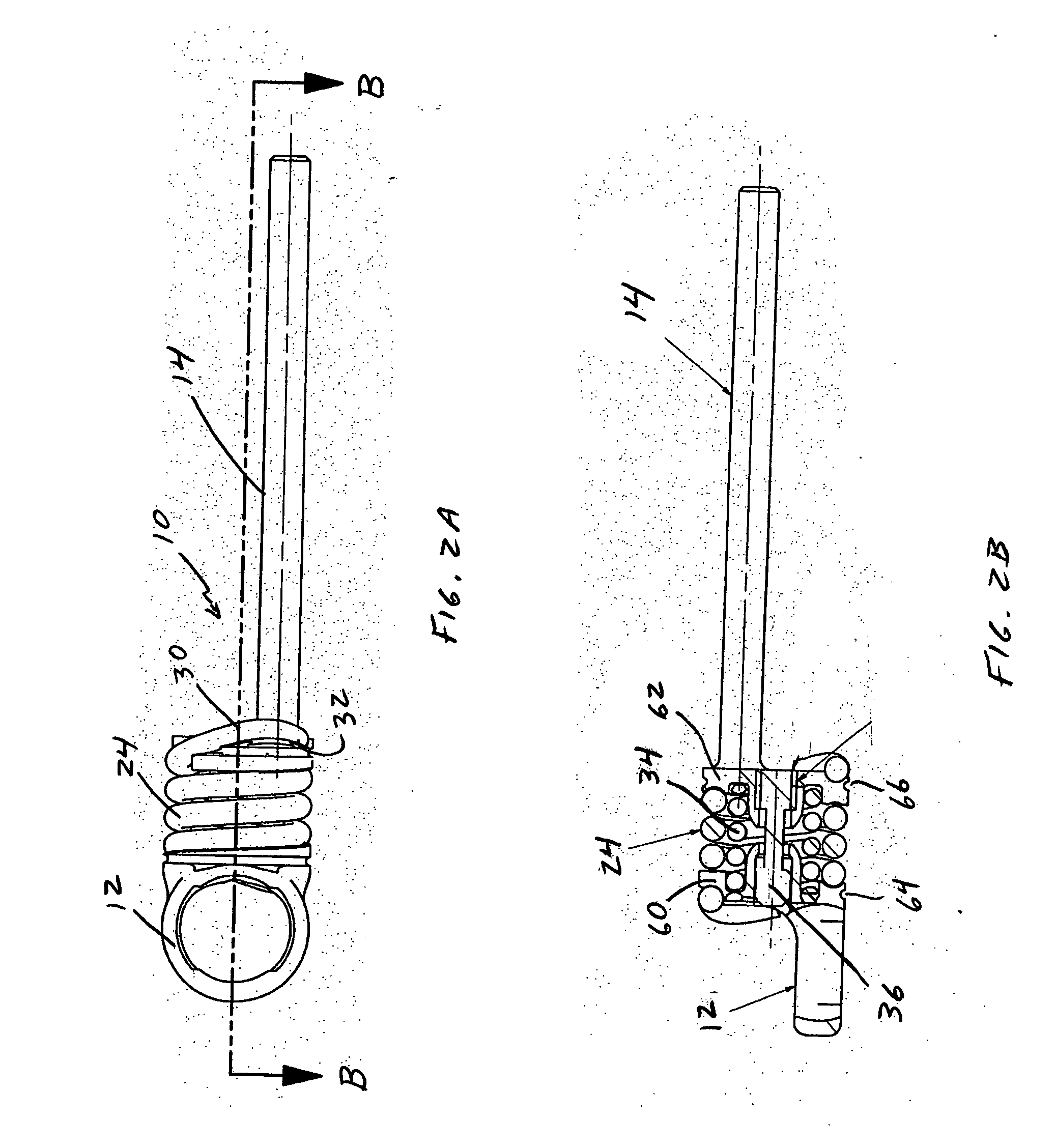
[0039] The present disclosure provides advantageous spinal stabilization systems and methods for assembling, fabricating and / or manufacturing such spinal stabilization systems. More particularly, the present disclosure provides advantageous sheath subassemblies that are configured and dimensioned to be mounted with respect to a spinal stabilization system. In exemplary embodiments of the present disclosure, the disclosed sheath subassemblies may be mounted with respect to dynamic element(s), e.g., spring member(s), that are adapted to provide dynamic stabilization to a spinal region, thereby encasing or otherwise enclosing the dynamic element(s) and protecting against potentially undesirable anatomical interaction between such dynamic element(s) and the surrounding anatomical elements / structures. Still further, the present disclosure provides advantageous methods and / or techniques for fabricating a sheath subassembly for assembly as part of a spinal stabilization device, e.g., a dy...


PUM


Abstract

Systems, assemblies and methods for assembling a sheath member with respect to a spinal stabilization device are provided. The disclosed sheath assembly includes at least one connector ring mounted with respect to a sheath member. The connector ring defines an inner wall that shields the sheath member from elements positioned therewithin, e.g., spring members, and generally includes a plurality of radially-spaced notches. The connector ring receives the sheath member within an internal cavity and is secured thereto by crimping, compression or swaging. The sheath assembly may be mounted with respect to a spinal stabilization device by crimping, compressing or swaging the connector ring to an underlying structure, e.g., an end cap or associated flange. The internal cavity of the connector ring is generally defined by an inner face, an outer wall and an intermediate apex region. Methods for assembly are also disclosed.

Description

CROSS-REFERENCE TO RELATED APPLICATIONS [0001] The present application is a continuation-in-part of a co-pending, commonly assigned U.S. patent application entitled “Surgical Implant Devices and Systems Including a Sheath Member,” which was filed on Dec. 31, 2004 and assigned Ser. No. 11 / 027,073. The entire contents of the foregoing patent application are incorporated herein by reference.BACKGROUND [0002] 1. Technical Field [0003] The present disclosure is directed to a system and method for assembling a sheath with respect to a spinal stabilization device. More particularly, the present disclosure is directed to a sheath subassembly that includes at least one connector ring mounted with respect to a sheath member, and methods for fabricating the sheath subassembly and subsequently mounting the sheath subassembly with respect to a spinal stabilization device. [0004] 2. Background Art [0005] Low back pain is one of the most expensive diseases afflicting industrialized societies. With...

Claims


Application Information

Patent Timeline
IPC IPC(8): A61F2/30
CPCA61B17/7004A61B17/7007A61B17/7041A61B17/7028A61B17/7035A61B17/7011
Inventor TIMM, JENS P.ANTHONY, JOHN
Owner APPLIED SPINE TECH
Why Eureka
Try Eureka