Intramedullary devices and methods of deploying the same

Inactive Publication Date: 2006-10-12
ORTHOMECHANICS
View PDF13 Cites 139 Cited by
  • Summary
  • Abstract
  • Description
  • Claims
  • Application Information

AI Technical Summary

Benefits of technology

[0016] The aforementioned needs are satisfied

Problems solved by technology

Unfortunately, despite their advantages, many intramedullary fixation devices known in the art are not completely satisfactory.
Generally speaking, it is revealed that many currently known devices fail to securely engage the inside of the medullary canal, thus providing only limited lateral support.
Unfortunately, this can allow for potential rotational and migratory movement of the bone fragments relative to one another.
Unfortunately, U.S. Pat. No. 6,575,973 does not disclose a method of effecting a reamed

Method used


Image

  • Intramedullary devices and methods of deploying the same
  • Intramedullary devices and methods of deploying the same
  • Intramedullary devices and methods of deploying the same

Examples


Embodiment Construction

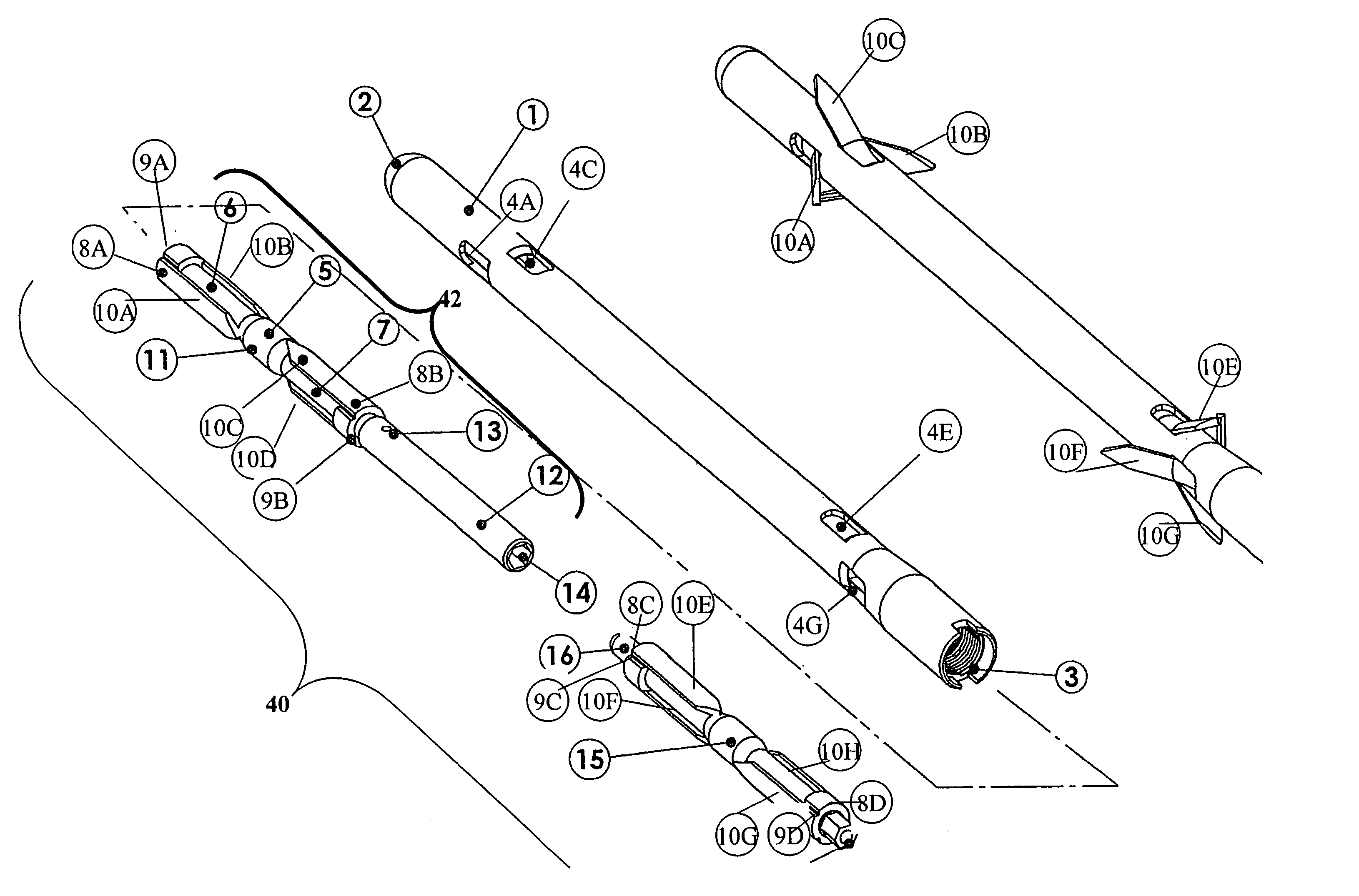
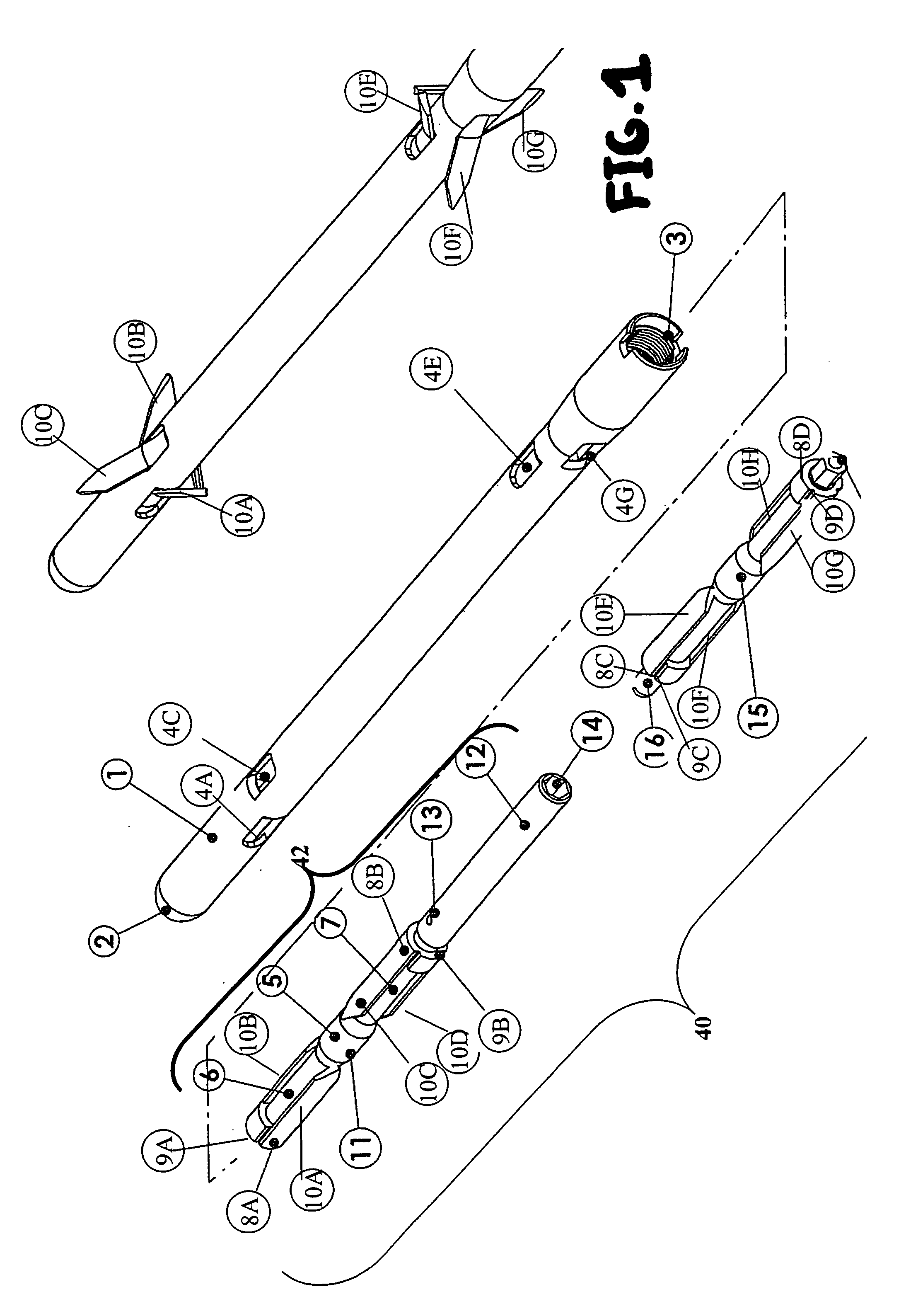
[0067] The present invention will now be described in terms of specific, example embodiments. It is to be understood that the invention is not limited to the example embodiments disclosed. It should also be understood that not every feature of the implantable devices and methods of treatment described is necessary to implement the invention as claimed in any particular one of the appended claims. Various elements and features of devices are described to fully enable the invention. It should also be understood that throughout this disclosure, where a process or method is shown or described, the steps of the method may be performed in any order or simultaneously, unless it is clear from the context that one step depends on another being performed first.

[0068] It will now be described an intramedullary nail to connect the fragments of a broken bone. The nail is locked to the proximal and distal fragments of the broken bone, allowing patients to bear weight on the bone early, thereby f...


PUM


Abstract

Internally locking intramedullary nails or devices and methods of deploying internally locking intramedullary nails are disclosed. According to some embodiments, the nail includes a cannulated sleeve, a plurality of anchoring elements, and one or more extension mechanisms for outwardly extending anchoring elements to anchor against movement along an elongated axis of the sleeve. Exemplary methods include but are not limit to methods of securing an internally locking intramedullary nail within a fracture bone, methods of effecting a reamed deployment of an internally locking intramedullary nail, and methods of modifying the extend to which anchoring elements are extended to effect dynamization useful for inducing bone growth. According to some embodiments, the internally locking intramedullary device includes a first extension mechanism operative to outwardly extend at least one anchoring element of a first set of anchoring elements through respective radially openings in the sleeve at an oblique position facing one end of the sleeve to anchor against movement in a longitudal direction and a second extension mechanism independent of or decoupled from the first extension mechanism operative to outwardly extend at least one anchoring element of a second set of anchoring elements through respective radially openings in the sleeve at an oblique position facing the opposite end of the sleeve to anchor against movement in the opposite longitudal direction. According to some embodiments, the intramedullary device includes a differential extension mechanism operative to extend anchoring elements through respective radial openings such that an increase in displacement of individual said anchor elements of first and second groups of anchoring elements generated by operation of the differential extension mechanism is distributed between the first and second groups as a function of resistance encountered by the first and second groups of anchoring elements. Some embodiments of the present invention provide hip prosthetic implant for replacing the proximal portion of a femur, where the implant includes at least one deformable clamping element for outwardly engaging surrounding bone tissue to anchor a stem portion of the implant within the intramedullary canal.

Description

CROSS-REFERENCE TO RELATED APPLICATIONS [0001] This application claims priority to U.S. Provisional Application Ser. No. 60 / 655,884, filed on Feb. 25, 2005, which is incorporated herein by reference in its entirety.FIELD OF THE INVENTION [0002] The invention relates to surgical devices for fixing broken bones and to hip implant devices. BACKGROUND OF THE INVENTION Intramedullary Devices [0003] Bone fractures are treated by realigning the broken bone fragments and immobilizing them in their formerly healthy positions relative to one another until the body causes the bone to heal and restore its structural integrity. Immobilization or fixation of the segments is accomplished by the use of rigid devices that span the fracture site and are located either external to the body or internally on the bone surface or inside the medullary canal. [0004] Intramedullary fixation devices, which are indicated primarily in the fracture of long tubular bones, offer substantial advantages over extern...

Claims


Application Information

Patent Timeline
IPC IPC(8): A61F2/30
CPCA61B17/7225A61F2250/0036A61B17/746A61F2/36A61F2/3662A61F2002/30324A61F2002/30405A61F2002/30451A61F2002/30546A61F2002/30565A61F2002/30579A61F2002/30774A61F2002/3611A61F2002/3625A61F2002/3682A61F2002/3696A61F2002/4638A61F2220/0025A61F2220/0058A61F2250/0012A61B17/7266A61F2002/368A61F2002/30594
Inventor MELLER, NIMRODSHEKALIM, AVRAHAMCOHEN, NIR
Owner ORTHOMECHANICS
Why Eureka
Try Eureka