System and methods utilizing slope of target speed for cooperative speed for cooperative speed control system

a speed control system and target speed technology, applied in process and machine control, navigation instruments, instruments, etc., can solve the problem that existing speed control systems still require a relatively substantial amount of input from the driver to alter the speed of the vehicl

Active Publication Date: 2006-10-12
NISSAN MOTOR CO LTD
View PDF12 Cites 30 Cited by
  • Summary
  • Abstract
  • Description
  • Claims
  • Application Information

AI Technical Summary

Problems solved by technology

However, existing speed control systems still require a relatively substantial amount of input from the driver to alter the speed of the vehicle.

Method used


Image

  • System and methods utilizing slope of target speed for cooperative speed for cooperative speed control system
  • System and methods utilizing slope of target speed for cooperative speed for cooperative speed control system
  • System and methods utilizing slope of target speed for cooperative speed for cooperative speed control system

Examples


first embodiment

[0048] a cooperative speed control system according to the present invention relates to a system that automatically changes a set speed (V_set) of a host vehicle, such as that set using the host vehicle's speed control system (e.g., cruise control, adaptive cruise control system (ACC), etc.) to a new set speed (V_set_new) based on a change in environmental conditions of the vehicle, such as by way of example, a change in speed limit. The change in environmental condition may be communicated to the vehicle in a variety of ways, such as, for example, via a wireless radio broadcast from an infrastructure communication device received by a radio onboard the host vehicle.

[0049] An exemplary scenario implementing the first embodiment will now be described, followed by a more detailed description of some other embodiments of the invention.

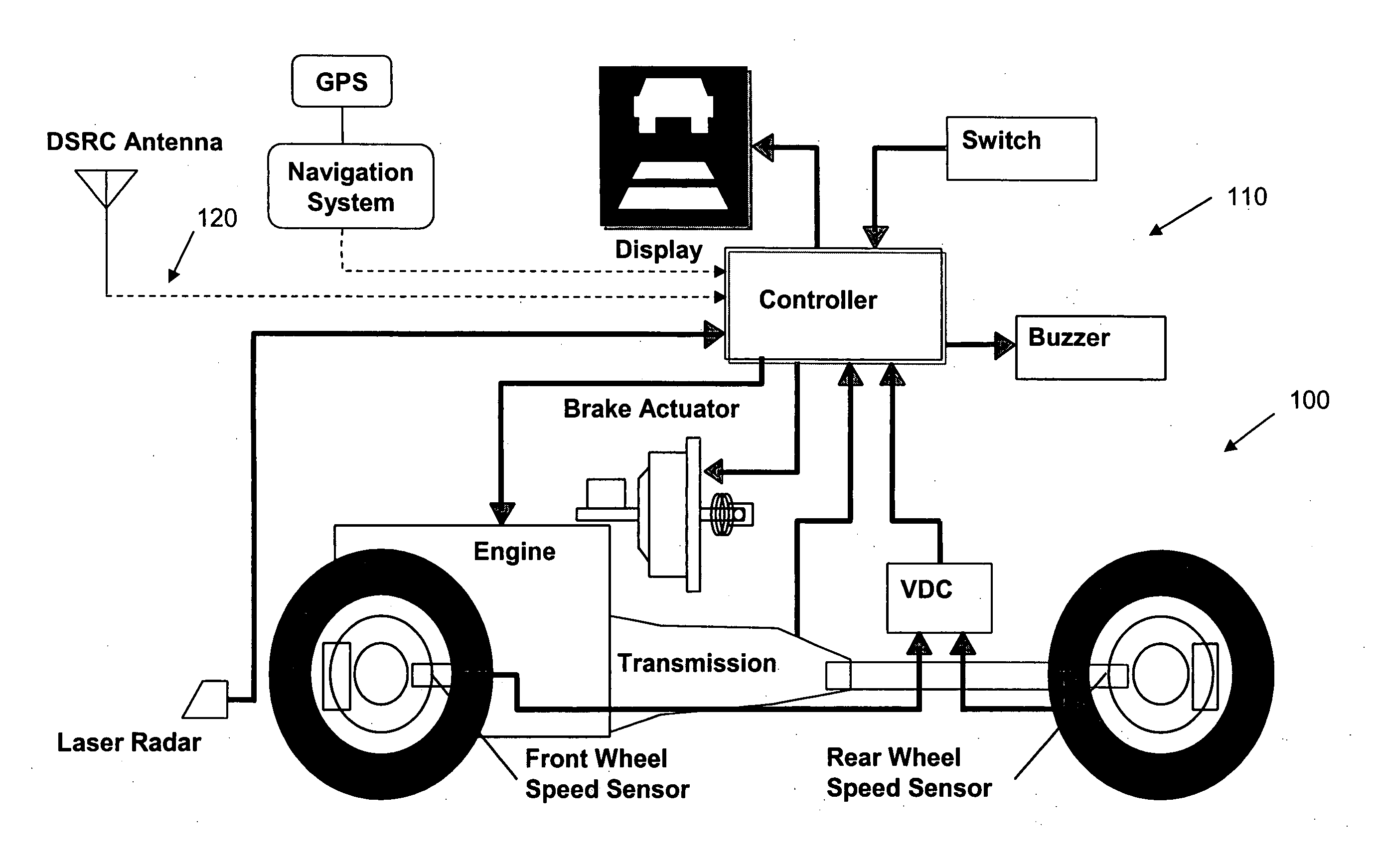
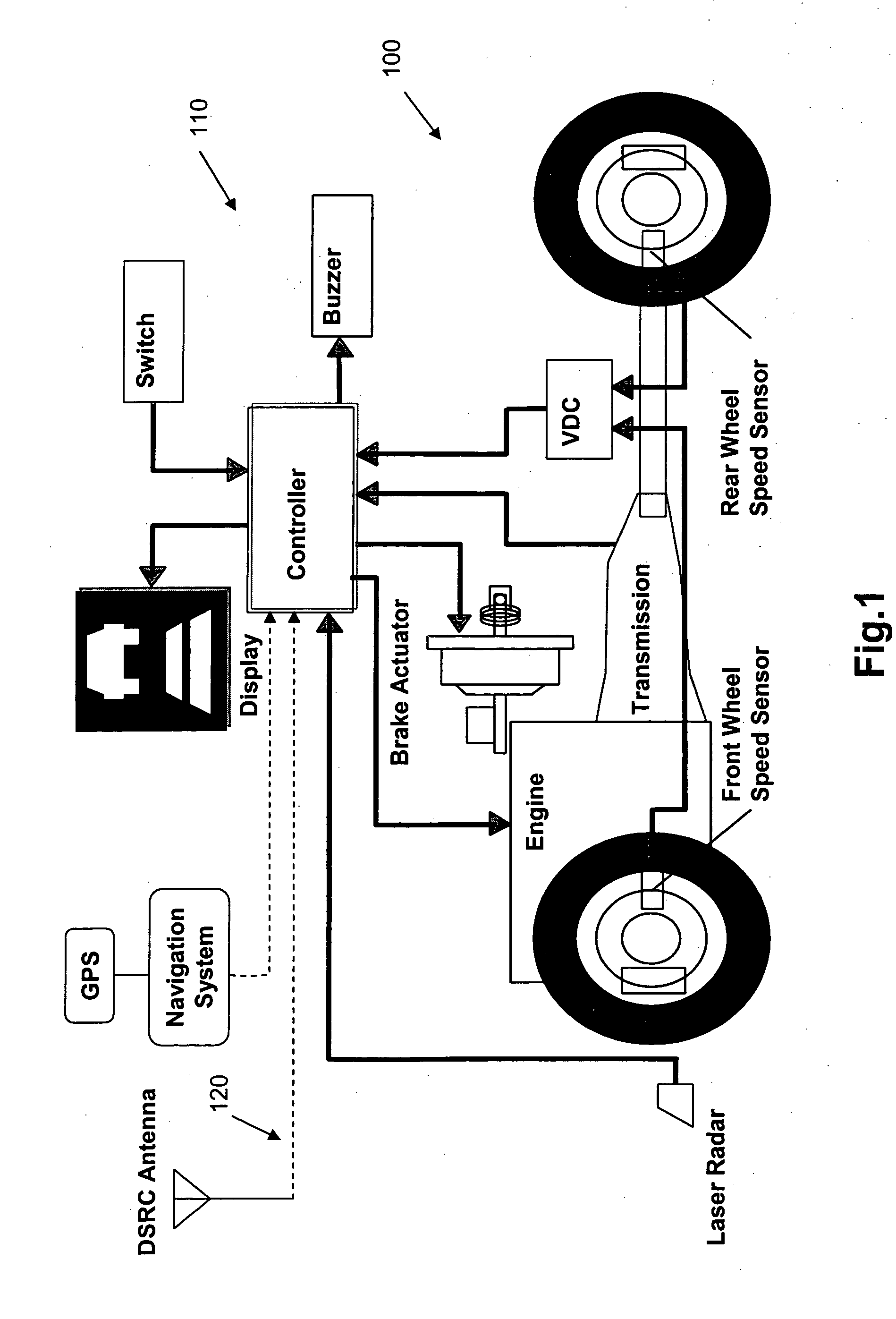
[0050] In an exemplary scenario, there is a host vehicle 100 that is traveling down a roadway having a cooperative speed control system according to the...

second embodiment

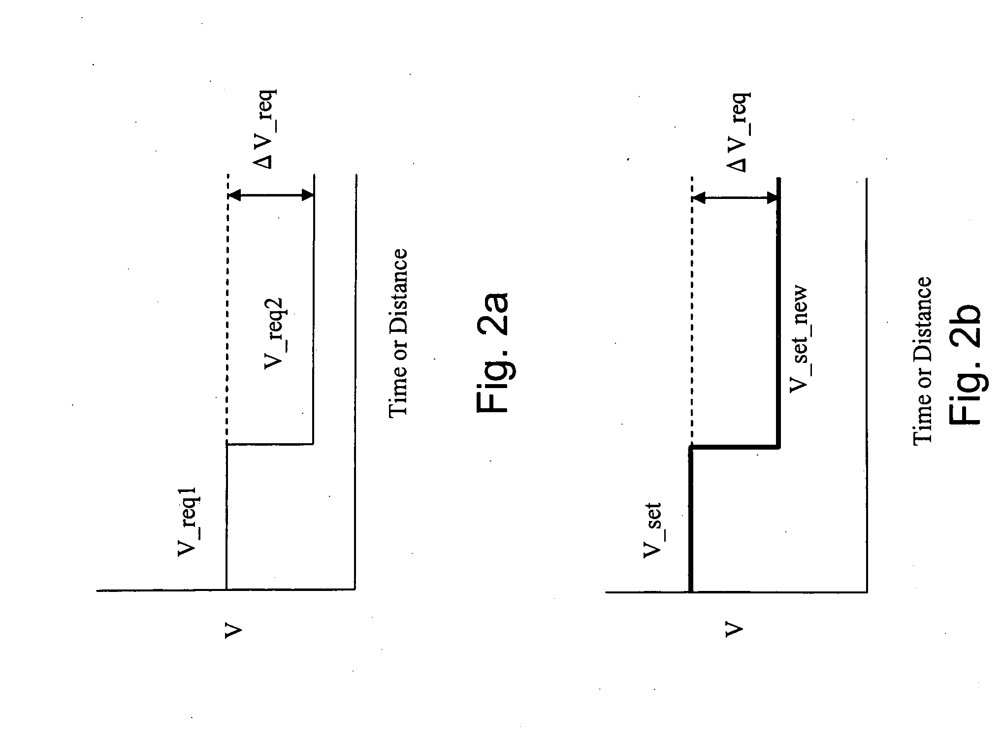
[0056] In a second embodiment according to the present invention, the set speed (V_set) is again changed based on a differentiation in speed between the first required speed (V_req1) and the second required speed of the vehicle (V_req2). However, the differentiation in speed is now in the form of a ratio of the second required speed to the first required speed. That is, the new set speed is determined based on a ratio of the second required speed (V_req2) and the first required speed (V_req1). That is, instead of changing the set speed by the exact difference between V_req1 and V_req2 in a one-to-one relationship, the set speed is changed by adjusting to the set speed based on a ratio of V_req2 and V_req1. Thus, V_set_new may be determined based on the equation

V_set_new=V_set*α—ΔV  (3)

where

α—ΔV=V—req2 / V—req1  (4).

In an exemplary scenario according to this second embodiment, if V_req1 is 65 miles per hour, and V_req2 is 50 miles per hour, α_ΔV would be about 0.77 (50 divided by ...


PUM


Abstract

A device for automatically controlling vehicle speed, including a processor, wherein the processor includes logic to determine a vehicle acceleration rate value, wherein the processor is configured to receive at least a first signal indicative of a first local required speed, a second signal indicative of a second local required speed received after the first signal, a third signal indicative of a value of a current vehicle speed, and information that enables the processor to determine the vehicle acceleration rate value, wherein the processor further includes logic to automatically determine a new set vehicle speed based at least on the first local required speed, the second local required speed, the current vehicle speed, and the determined vehicle acceleration rate value, and automatically initiate output of a signal to a vehicle speed controller to change vehicle speed to the new set vehicle speed.

Description

BACKGROUND OF THE INVENTION [0001] Speed control systems such as cruise control systems and adaptive cruise control system (ACC) are common on vehicles. Even car owners who do not have speed control systems in their own vehicles are typically familiar with such devices and often easily implement the use of the speed control systems when using vehicles with such systems. Drivers often find it convenient to set a desired speed for the vehicle and allow the speed control system to maintain the speed of the vehicle at the set speed. However, existing speed control systems still require a relatively substantial amount of input from the driver to alter the speed of the vehicle. For example, when a speed limit changes from one speed to another, for example, from 50 miles per hour to 65 miles per hour, and the speed control system was previously set to maintain a vehicle speed of just below 50 miles per hour, the driver must affirmatively change the set speed of the vehicle control system t...

Claims


Application Information

Patent Timeline
Patent Type & Authority Applications(United States)
IPC IPC(8): G01C21/00B60W30/16
CPCB60W30/16B60W40/04B60W2550/148B60W2550/402Y10T477/816Y10T477/80Y10T477/81Y10T477/813Y10T477/814G01D5/00B60W2552/40B60W2556/50
Inventor KAWAZOE, HIROSHITSUDA, HIROSHI
Owner NISSAN MOTOR CO LTD
Why Eureka
Try Eureka