Locking mechanism for an extension pole

a locking mechanism and extension pole technology, applied in the field of extension poles, can solve the problems of deficient type of locking mechanism, pole may unexpectedly collapse, and the locking mechanism fails to provide infinite adjustability, so as to prevent the relative rotation between the bodies and prevent the relative shifting of the bodies

Inactive Publication Date: 2006-10-19
SPECIALTY PROD OF GREENWOOD MISSOURI
View PDF18 Cites 21 Cited by
  • Summary
  • Abstract
  • Description
  • Claims
  • Application Information

AI Technical Summary

Benefits of technology

[0006] The present invention overcomes the problems outlined above and provides an improved extension pole having an easy-to-operate locking mechanism requiring only a minimum of hand force to effect operation thereof, while at the same time effecting a secure pole lock. According to one aspect of the present invention, the extension pole includes an elongated outer tubular body and an elongated inner body telescoped within the outer body. The inner body is shiftable relative to the outer body in order to vary the length of the pole. The pole also includes a locking mechanism that comprises a stationary component secured to the outer body and a shiftable component. The shiftable component has a mounting segment disposed about the stationary component, and a locking segment extending from the mounting segment and proximal to the inner body. The locking mechanism being in an unlocked condition thereof to permit relative shiftable movement between the inner and outer bodies. The locking mechanism being placed in a locked condition upon shifting of the shiftable component to cause the locking segment to engage the inner body and thereby hold the inner body relative to the outer tubular body.
[0007] In another aspect of the invention, the extension pole includes an elongated outer tubular body and an elongated inner body telescoped within the outer body. The bodies are relatively shiftable along a pole axis in order to vary the length of the pole. The pole also includes a locking mechanism operable to selectively prevent relative shifting of the bodies. The locking mechanism includes a shiftable component positionable in a locked position, in which movement of the bodies is prevented, and an unlocked position, in which relative shifting of the bodies is permitted. The shiftable component of the locking mechanism includes a locking segment that is fixed axially relative to a first one of the bodies, such that a second one of the bodies is axially shiftable relative to the locking segment. The second one of the bodies includes a body surface that presents a centerline that is at least substantially coaxial with the pole axis. The locking segment includes a segment surface that presents a centerline, with the segment surface extending at least partly around the body surface of the second one of the bodies. The centerline of the locking segment is substantially aligned with the pole axis when the shiftable component is in said unlocked position thereof. On the other hand, when the shiftable component is in the locked position, the centerline of the locking segment is moved to an offset position relative to the pole axis, such that the locking segment engages the second one of the bodies and thereby prevents relative shifting of the bodies.
[0008] Yet another aspect of the present invention concerns an extension pole including an elongated outer tubular body and an elongated inner body telescoped within the outer body. The bodies are relatively shiftable along a pole axis in order to vary the length of the pole. The pole also includes a locking mechanism operable to selectively prevent relative shifting of the bodies. The locking mechanism includes a stationary component secured to a first one of the bodies and a relatively rotatable component positionable in a locked position, in which movement of the bodies is prevented, and an unlocked position, in which relative shifting of the bodies is permitted. The second one of the bodies and at least one of the first body and the stationary component present slidably engaging, axially extending surfaces. The surfaces have complemental segmented circular shapes including at least one arcuate section and at least one chord section, such that relative rotation between the bodies is prevented.

Problems solved by technology

However, this type of locking mechanism fails to provide infinite adjustability.
This type of locking mechanism has been found to be deficient because it requires considerable manual force to move the mechanism between the locked and unlocked positions thereof.
This construction can also be problematic because a user may not apply sufficient force to fully lock the pole in a selected extended position, and consequently the pole may unexpectedly collapse during use.

Method used


Image

  • Locking mechanism for an extension pole
  • Locking mechanism for an extension pole
  • Locking mechanism for an extension pole

Examples


Embodiment Construction

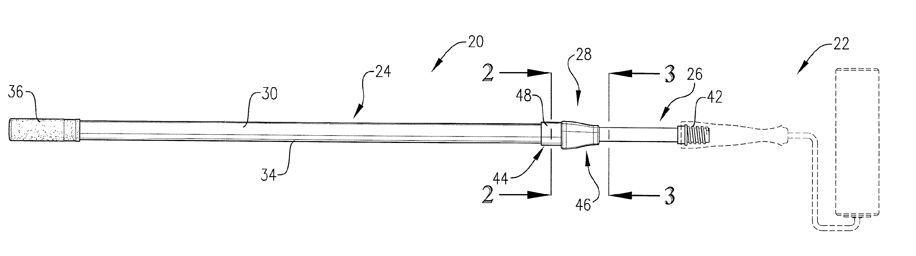
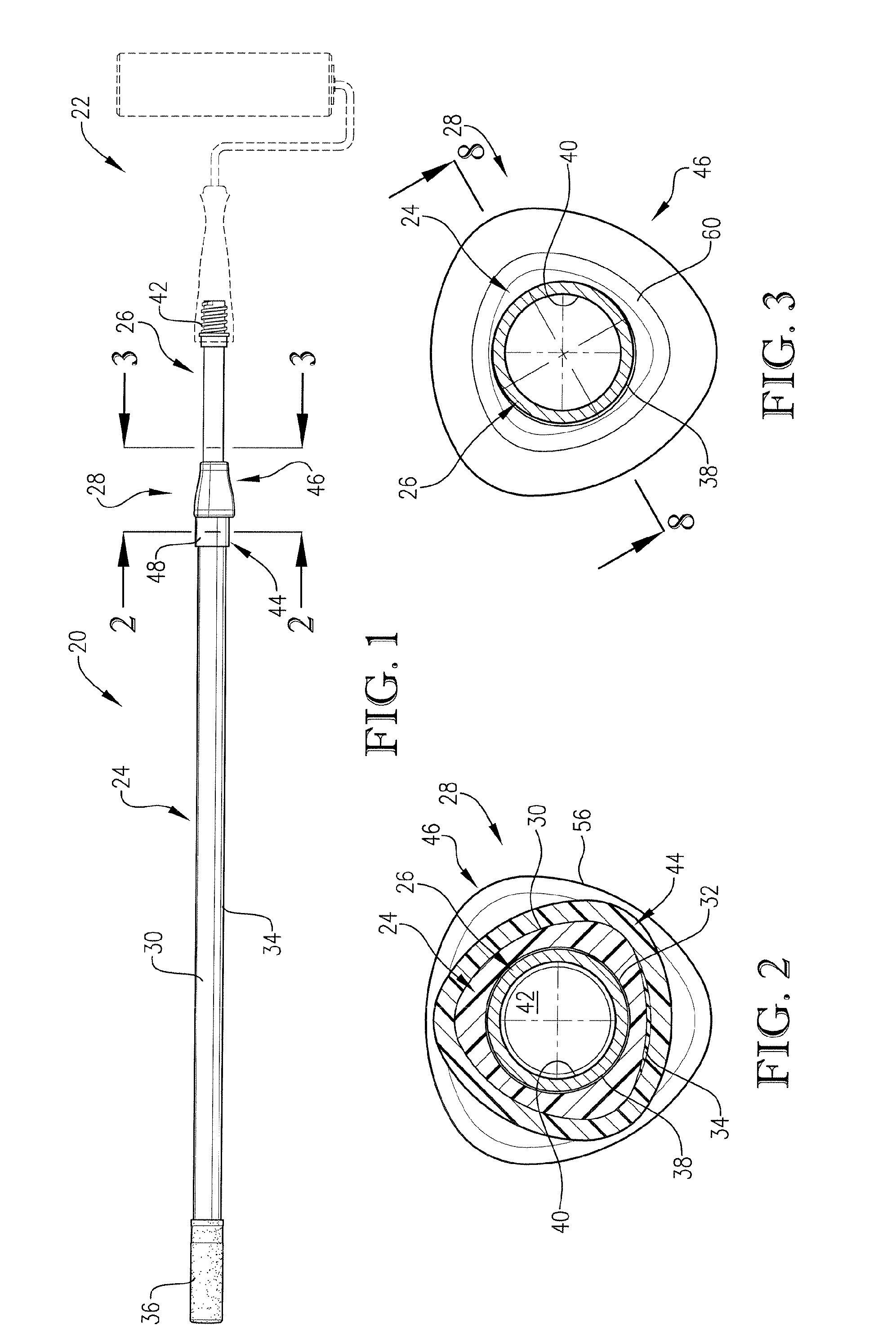
[0028] Turning now to the drawings, FIG. 1 illustrates an extension pole 20 in accordance with the invention, shown supporting an exemplary working tool, in this case a paint roller 22. It will be understood that the pole 20 can be used with a variety of different tools, well known to those skilled in the art.

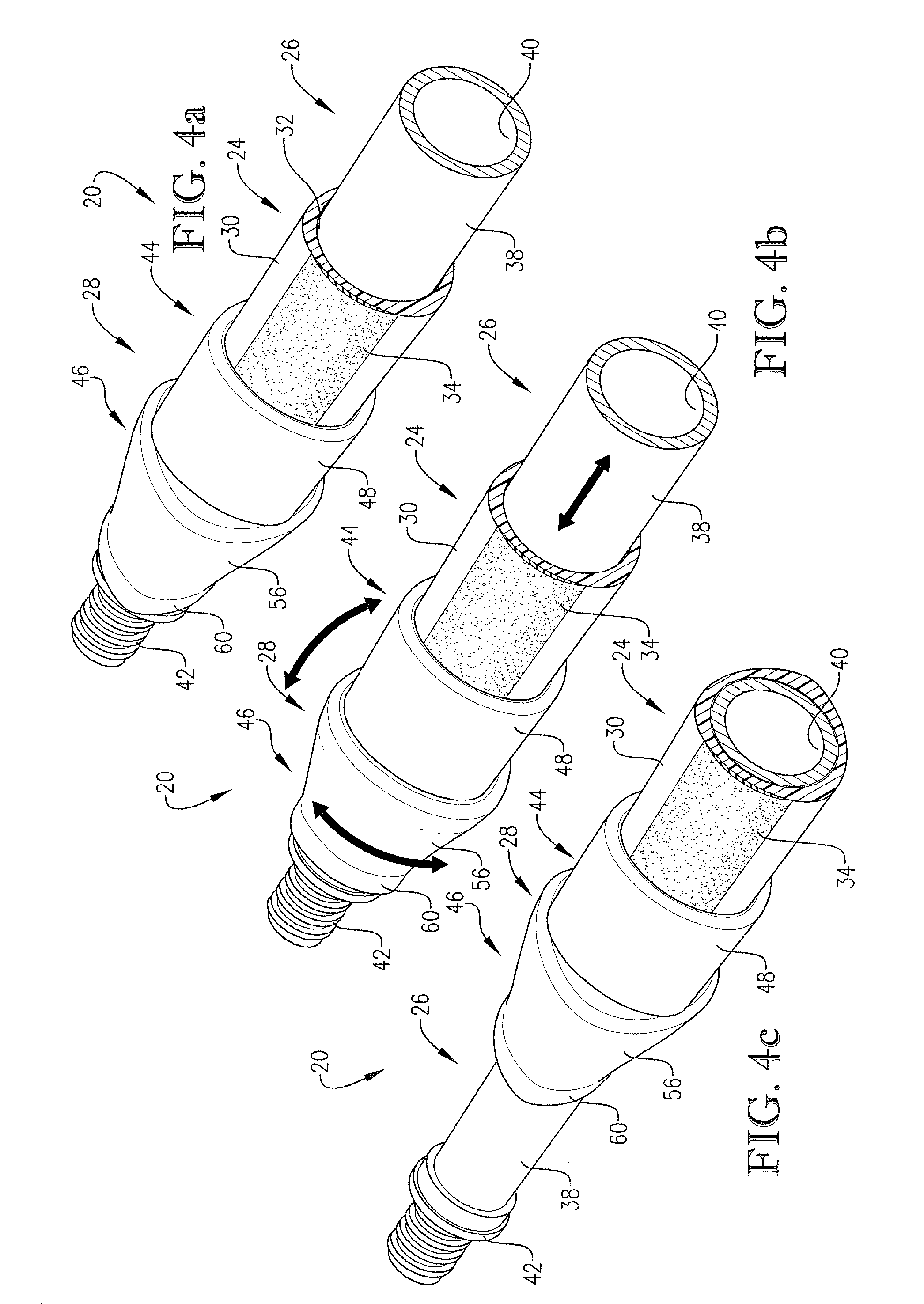
[0029] Broadly speaking, the pole 20 includes an elongated outer tubular body 24, an elongated inner body 26 telescopically received within body 24, and a locking mechanism 28 operatively coupled to the poles sections 24, 26. As explained in more detail hereinafter, the pole 20 is designed to allow the user to quickly and easily adjust the effective length of the pole 20 as desired, while also assuring that the pole in its extended position is securely locked against inadvertent collapse.

[0030] In more detail, the outer body 24 is in the form of an elongated tube. The illustrated body 24 preferably presents a polygonal (i.e., somewhat triangular) outer gripping surface 30 wit...


PUM


Abstract

An improved extension pole (20) is provided having relatively shiftable outer and inner bodies (24, 26) with a manually operable locking mechanism (28). The mechanism (28) includes a stationary component (44) secured to outer body (24), with a bidirectionally rotatable component (46) supported on the component (44). The rotatable component (46) has a projecting locking segment (60) disposed about the inner body (24), with the segment (60) being offset. When the mechanism (28) is in its unlocked condition, the centerline of the segment (60) is substantially coincident with the centerlines of the inner and outer bodies (24, 26), thereby permitting free reciprocation of body (26); upon rotation of the component (46), the locking segment (60) comes into direct, frictional, locking engagement with the inner body (26) along a contact arc (68).

Description

BACKGROUND OF THE INVENTION [0001] 1. Field of the Invention [0002] The present invention is broadly concerned with extension poles having at least a pair of telescopically interfitted bodies allowing the length of the pole to be adjusted by the user. More particularly, the invention is concerned with such extension poles having an improved, bidirectionally operable locking mechanism coupled between the relatively shiftable bodies and which allows the user to easily and quickly engage and disengage the locking mechanism using only a minimum of physical effort. [0003] 2. Description of the Prior Art [0004] Tool-supporting extension poles are used to extend the reach of a user for the application of a tool, such as a paint roller, to hard-to-reach locations, such as a ceiling or the upper portion of a wall. Generally speaking, these prior poles have included an outer tubular section with an inner section telescoped within the outer section and selectively shiftable relative thereto. S...

Claims


Application Information

Patent Timeline
Patent Type & Authority Applications(United States)
IPC IPC(8): B25G1/04
CPCB05C17/0205Y10T16/473B25G1/04
Inventor RICHARDSON, WILLIAM DANIELPOOLE, DWIGHT R.
Owner SPECIALTY PROD OF GREENWOOD MISSOURI
Why Eureka
Try Eureka