Combustor and cap assemblies for combustors in a gas turbine

a gas turbine and combustible technology, applied in the combustion process, hot gas positive displacement engine plant, lighting and heating apparatus, etc., can solve the problems of excess cap assembly hardware having the lower rated hours of operation, and thus constitute stranded assets

Inactive Publication Date: 2006-10-19
GENERAL ELECTRIC CO
View PDF8 Cites 21 Cited by
  • Summary
  • Abstract
  • Description
  • Claims
  • Application Information

AI Technical Summary

Benefits of technology

[0005] In a further preferred embodiment of the present invention there is provided a combustor comprising: a combustor liner; a cap assembly in part received within an end of the liner; a seal between the cap assembly part and said liner including pair of generally annular rings with each said ring having a plurality of spring fingers at circumferentially spaced locations thereabout, said rings being concentrically disposed relative to one another with the spring fingers of one ring circumferentially offset from the spring fingers of another ring enabling the spring fingers of each ring to register with gaps between the spring fingers of said another ring.

Problems solved by technology

This has led to an excess supply of cap assembly hardware having the lower rated hours of operation.
These excess cap assemblies thus constitutes stranded assets since the lower rated cap assemblies would not be utilized in upgraded or providing new cap assemblies in new turbines.

Method used


Image

  • Combustor and cap assemblies for combustors in a gas turbine
  • Combustor and cap assemblies for combustors in a gas turbine
  • Combustor and cap assemblies for combustors in a gas turbine

Examples


Embodiment Construction

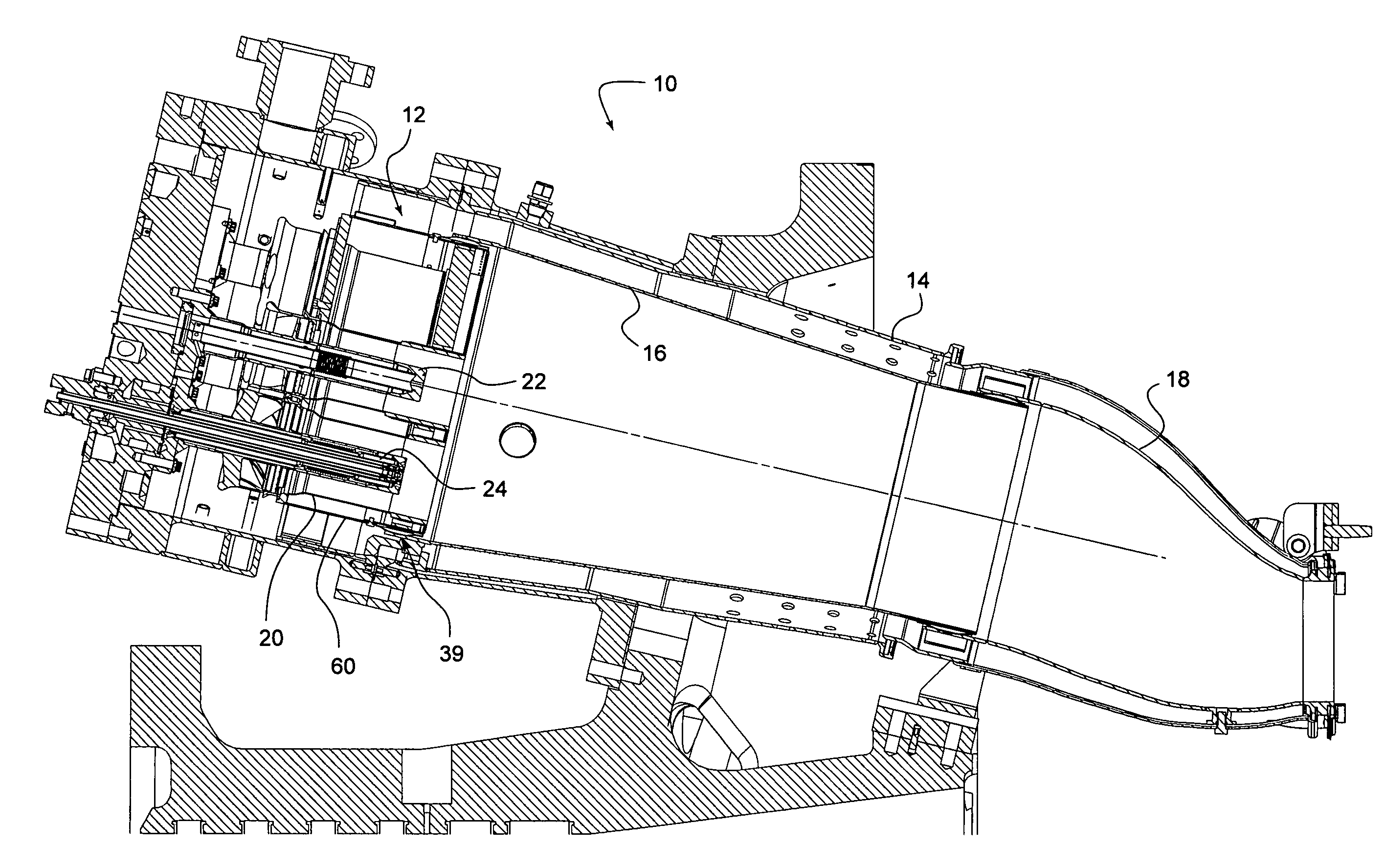
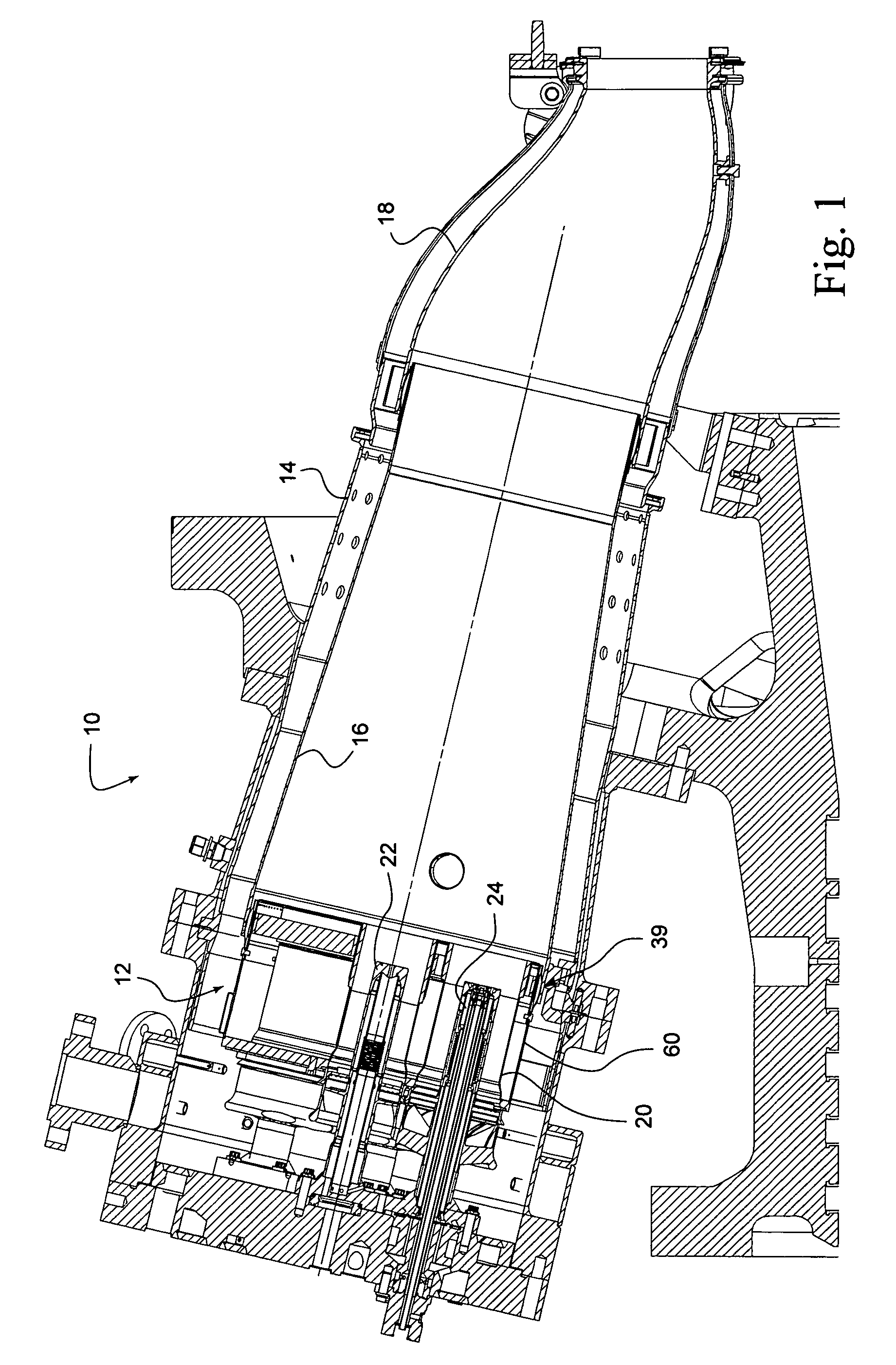
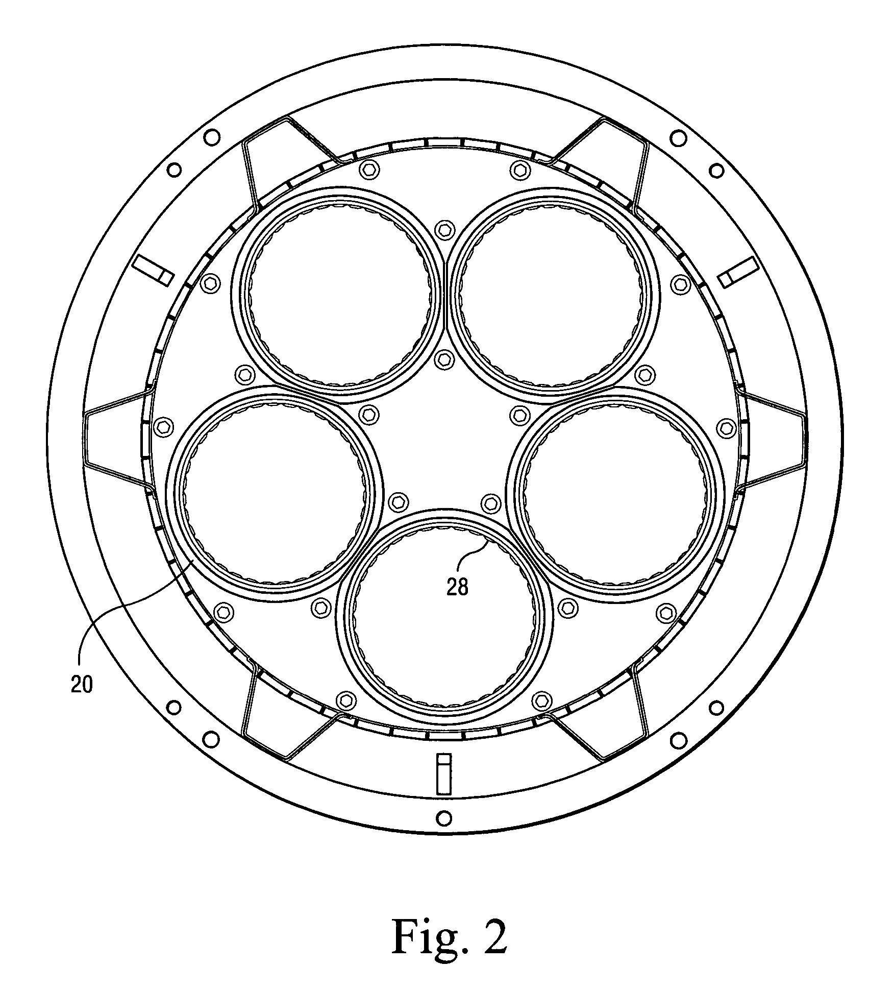
[0018] Referring now to the drawings, particularly to FIG. 1, there is illustrated a combustor generally designated 10 for a gas turbine. Combustor 10 includes a cap assembly generally designated 12 at a forward end of the combustor. As is conventional, combustor 10 includes a flow sleeve 14, a combustor liner 16 and a transition piece 18. Additionally, the cap assembly 12 includes a plurality of burner tubes 20 which form an annular array of tubes about the axis of the combustor and about a central fuel nozzle 22. Each burner tube 20 also houses a fuel nozzle 24 illustrated in FIG. 1. Typically, compressor discharge air is supplied to the burner tubes and fuel nozzle for mixing with fuel to enable combustion, the combustion gases flowing through the transition piece 18 into the turbine to extract work from the gases.

[0019] The burner tubes 20 typically have piston seals 28 for sealing about the burner tubes and to the fuel nozzle which is received within the burner tubes. Prior bu...


PUM


Abstract

The cap assembly of a turbine combustor includes a plurality of burner tubes sealed against fuel nozzles extending in the tubes. These piston seals are coated with a high velocity oxygen fuel coating to extend their service life. The outer cap body assembly includes concentric seal rings each with cantilevered convex fingers circumferentially offset from one another to seal between the cap assembly casing and the inner liner. The cap assembly casing is provided with a plurality of holes at predetermined locations about the casing to minimize or eliminate response to combustion dynamics.

Description

[0001] The present invention relates to combustors and cap assemblies for combustors having increased service life and particularly relates to combustors and cap assemblies therefor for converting combustors and cap assemblies having a predetermined life cycle to combustors and cap assemblies having extended life cycles. BACKGROUND OF THE INVENTION [0002] In gas turbines, a plurality of combustors are typically arranged in an annular array about the axis of the turbine. For example, in one known turbine, eighteen combustors are circumferentially spaced about the turbine axis. Each combustor combines fuel and compressor discharge air into an fuel / air mixture which is then combusted with the resulting gases expanded through the blades of the turbine whereby work is extracted from the turbine. [0003] Combustors including cap assemblies are typically rated for a predetermined number of hours of operation before requiring service. For example, a cap assembly may be rated for 8,000 hours ...

Claims


Application Information

Patent Timeline
Patent Type & Authority Applications(United States)
IPC IPC(8): F23R3/42
CPCF23R3/10F23R3/60F23R3/46
Inventor JOHNSON, JERE A.BAILEY, MARKBERRY, ROBERT R.BEITZ, STEWART W.MONAGHAN, JAMES C.
Owner GENERAL ELECTRIC CO
Why Eureka
Try Eureka