Attachment for a saw

Inactive Publication Date: 2006-10-19
FIGURSKI ADAM J
View PDF11 Cites 5 Cited by
  • Summary
  • Abstract
  • Description
  • Claims
  • Application Information

AI Technical Summary

Benefits of technology

[0018] The present invention is an inexpensive, foolproof attachment for simplifying the cutting of the ends of crown molding. A pair of attachments is light and takes up little space in a toolbox. The attachments can be mounted upon a saw in seconds and without measuring or adjusting the support angle. The attachments do not damage the saw and do not require that any holes be drilled in the base or fence; no adhesive or tools are required. Bec

Problems solved by technology

Crown molding has the reputation of being very difficult to cut and install, largely due to the need for compound angles.
In the case of crown molding, though, the spring angle affects the set up of the cutting angle.
Inexperienced persons frequently make many incorrect cuts before realizing the problem.
Wrong cuts are frustrating, waste time, and

Method used


Image

  • Attachment for a saw
  • Attachment for a saw

Examples


Embodiment Construction

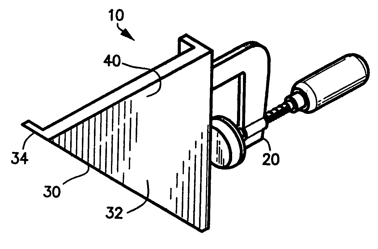
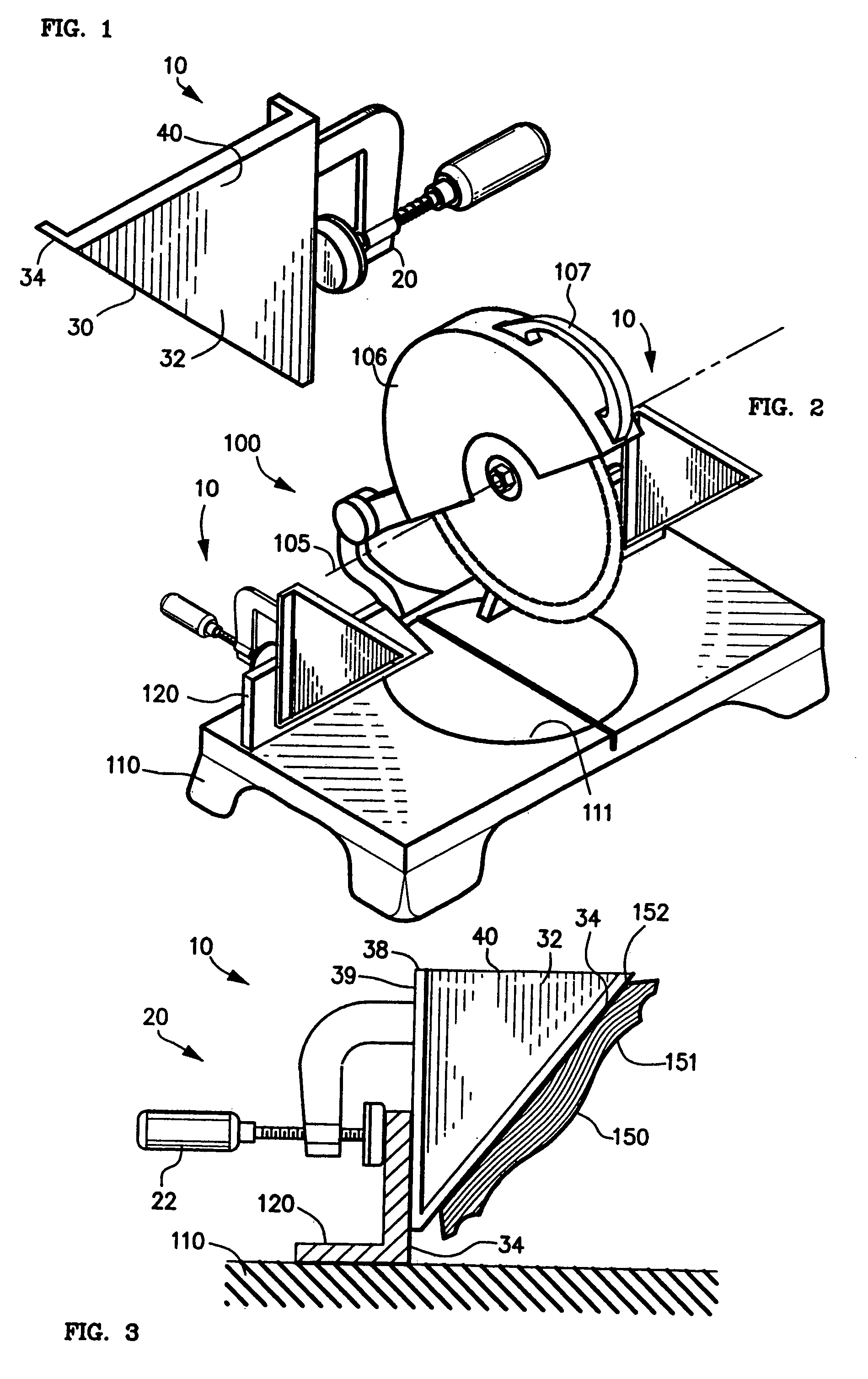
[0023]FIG. 1 is a perspective view of a preferred embodiment of a single attachment 10 of the present invention. Attachment 10 generally includes mounting means 20 for mounting attachment 10 on a saw and supporting means 30 for supporting a piece of crown molding during cutting. Supporting means 30 includes a support area 34 defining a support plane. Angle means 40 attached between mounting means 20 and support area 34 disposes support angle at a predetermined dihedral angle relative to the fence, typically the spring angle of the crown molding.

[0024] Angle means 40 in the preferred embodiment 10 illustrated is a right triangle 32 having a hypotenuse that is angled, relative to the vertical fence, at the spring angle of the crown molding. Support area 34 is a widened area, such as a flange, connected along the hypotenuse of triangle 32.

[0025]FIG. 2 is a perspective view of an exemplary chop saw 100 with a pair of attachments 10, each attachment 10 mounted upon a fence 120. Chop sa...


PUM

PropertyMeasurementUnit
Angleaaaaaaaaaa
Areaaaaaaaaaaa

Abstract

Attachment for a saw simplifies cutting of crown molding by supporting molding at “spring” angle during cutting. Attachment includes clamp for removably mounting attachment on saw fence, and a right triangle having a hypotenuse congruent with “spring” angle. Attachment makes possible cutting of compound angle using only miter adjustment of saw.

Description

FIELD OF THE INVENTION [0001] This invention relates in general to attachments for saws and more specifically to workpiece supporting attachments for circular saws. BACKGROUND OF THE INVENTION [0002] Crown molding is an ornamental strip of wood or plastic that is used to cover a seam or joining in a building, such as the joining of a wall and ceiling. [0003] A widely used style of crown molding is known as “52 / 38” molding. Such molding has an ornamental face, typically with linear design motifs, which faces down into the room, and a plain face that faces the dihedral corner. The plain face includes a flat back and two beveled ends that fit generally flush against the wall and ceiling such that the flat back is disposed at an angle of 38° to the vertical wall and 52° to the horizontal ceiling. This is known as a “spring angle” of 52 / 38. [0004] Pieces of crown molding are typically cut to size with a “chop” or “end cut” saw. Chop saws have a circular blade in a housing that is pivotab...

Claims


Application Information

Patent Timeline
IPC IPC(8): B26D7/02
CPCB27B27/04Y10T83/7573Y10T83/7697
Inventor FIGURSKI, ADAM J.
Owner FIGURSKI ADAM J
Why Eureka
Try Eureka