Multi-axis load rollers for an industrial vehicle

a technology of industrial vehicles and load rollers, which is applied in the direction of hand carts, sledge wheels, transportation and packaging, etc., can solve the problems of loading instability or dislocation, significant vibration in the forks and vehicle frame, and discomfort during the operation of pallet trucks, so as to achieve stable and controllable support

Inactive Publication Date: 2006-10-19
HYSTER YALE GRP
View PDF3 Cites 40 Cited by
  • Summary
  • Abstract
  • Description
  • Claims
  • Application Information

AI Technical Summary

Benefits of technology

[0008] A load roller assembly includes a first load roller that rotates about a first axis, a second load roller that rotates about a second axis, and a third load roller that rotates about a third axis. The first and second load rollers are configured to move vertically up and down independently of the third load roller. This independent movement of the first and second axes provides more stable and controllable support to the front end of lift truck forks.

Problems solved by technology

As the pallet truck is operated over uneven or unimproved surfaces, the steer wheel and load rollers tend to move up and down in irregular patterns causing significant vibration in the forks and vehicle frame.
This vibration is transmitted through a steering handle to the operator and may result in discomfort during operation of the pallet truck.
The vibrations also shake loads on the forks potentially causing the loads to become unstable or dislodged.
The vibrations also create a significant amount of noise that can create a dangerous work environment or at the least be a nuisance to the operator and any bystanders.
The vertical movements may also cause the load rollers to temporarily lose contact and traction with the ground making it more difficult to operate the lift truck.

Method used


Image

  • Multi-axis load rollers for an industrial vehicle
  • Multi-axis load rollers for an industrial vehicle
  • Multi-axis load rollers for an industrial vehicle

Examples


Embodiment Construction

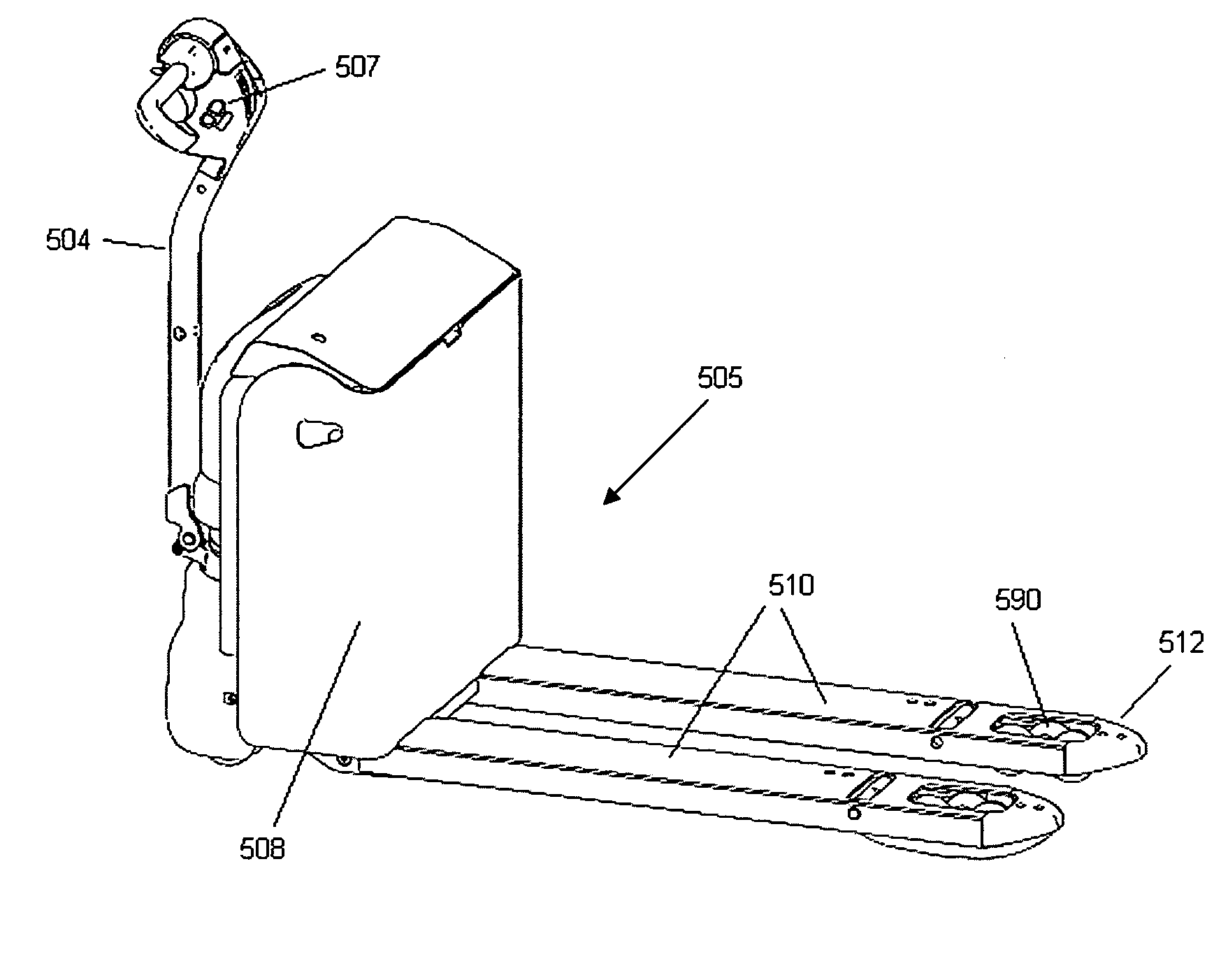
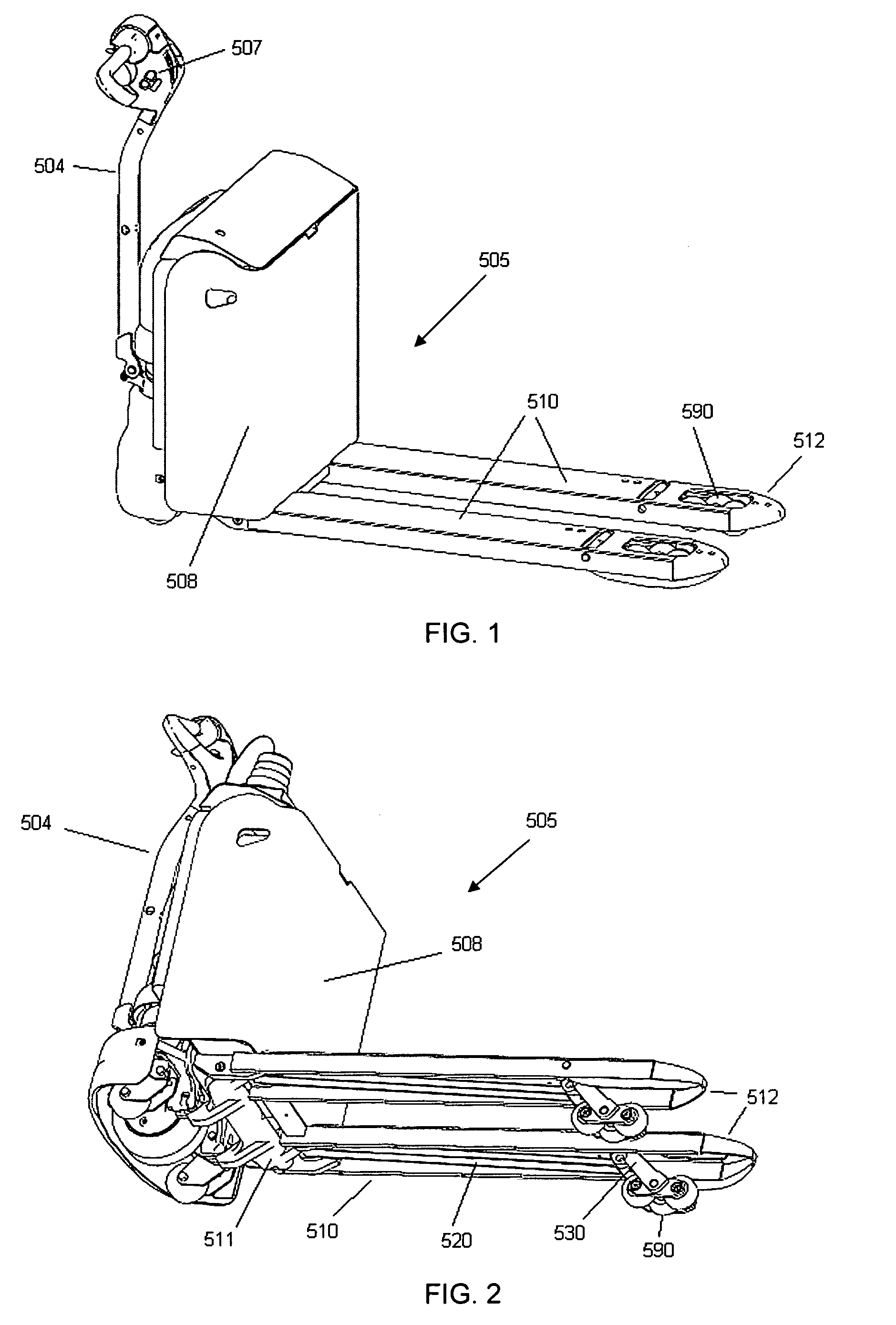
[0015]FIG. 1 shows an industrial pallet truck 5 that includes a fork 10 and a wheel assembly 590. It can be seen from FIG. 1 that the pallet truck 5 may include two forks, each nearly identical to fork 10. Furthermore, the pallet truck 5 is shown to include a vehicle frame 8 and a steer arm 4 by which the pallet truck is guided. The fork 10 is shown having a fork end 512 located on the opposite end of the fork 10 from the vehicle frame 8.

[0016] The steer arm 4 may include electronic or mechanical controls that raise and lower the fork 10 or that activate a traction motor (not shown) residing in the vehicle frame 8. It is understood that the pallet truck 5 shown is merely one example of a type of industrial lift truck that could be used with the present invention. For example, a motorized rider pallet truck may include an extended frame upon which an operator may stand while the motorized rider pallet truck is being operated. Other industrial lift trucks employing forks are similarl...


PUM


Abstract

A load roller assembly includes a first load roller that rotates about a first axis, a second load roller that rotates about a second axis, and a third load roller that rotates about a third axis. The first and second load rollers are configured to move vertically up and down independently of the third load roller. This independent movement of the first and second axes provide more stable and controllable support to the front end of lift truck forks.

Description

[0001] This application claims priority from U.S. Provisional Application 60 / 672,148, filed Apr. 14, 2005, and herein incorporated by reference.BACKGROUND OF THE INVENTION [0002] The invention relates to a transportation device used primarily in a materials handling vehicle such as an industrial pallet truck. [0003] Industrial pallet trucks known in the art typically include a drive or steer wheel located proximately under a vehicle frame of the pallet truck. The steer wheel may include a single tire or dual-tire construct. Two or more load wheels or load rollers are typically located near an end of the pallet truck opposite the vehicle frame, and underneath two forks. The steer wheel is used for maneuvering the pallet truck and the load rollers support the majority of the weight of a transported load carried on the pallet truck forks. [0004] Such pallet trucks may be powered by an electric motor or may be manually pulled or pushed by an operator. Electrically powered pallet trucks ...

Claims


Application Information

Patent Timeline
Patent Type & Authority Applications(United States)
IPC IPC(8): B62D21/14
CPCB62B3/008B62B3/0612B62D51/04B62B2301/08B62D51/02B62B5/02
Inventor PASSERI, GIANNI
Owner HYSTER YALE GRP
Why Eureka
Try Eureka