Reducing interference between multiple infra-red depth cameras

A technology of depth camera and infrared camera, which can be applied to color TV parts, TV system parts, instruments, etc., and can solve problems such as accuracy degradation

Active Publication Date: 2012-08-15
MICROSOFT TECH LICENSING LLC
View PDF4 Cites 28 Cited by
  • Summary
  • Abstract
  • Description
  • Claims
  • Application Information

AI Technical Summary

Problems solved by technology

This provides views of the scene from different angles and enables 360° models of objects to be constructed, but the accuracy of each IR depth camera is degraded in case of overlapping structured light patterns

Method used


Image

  • Reducing interference between multiple infra-red depth cameras
  • Reducing interference between multiple infra-red depth cameras
  • Reducing interference between multiple infra-red depth cameras

Examples


Embodiment Construction

[0020] The detailed description provided below in connection with the accompanying drawings is intended as a description of examples of the invention and is not intended to represent the only forms in which examples of the invention may be constructed or used. This description sets forth the functionality of an example of the invention, and a sequence of steps for building and operating the example of the invention. However, the same or equivalent functions and sequences can be implemented by different examples.

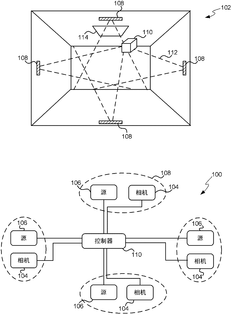
[0021] figure 1 A schematic diagram of an infrared depth camera system 100 is shown along with a perspective view of a room 102 showing an example deployment of the depth camera system 100 . figure 2 yes figure 1 A flowchart of an example method of operation of the depth camera system 100 shown in . System 100 includes multiple infrared (IR) cameras 104 and multiple IR sources 106 (only four cameras and four sources are shown in the figure as an example). Each I...


PUM


Abstract

Systems and methods for reducing interference between multiple infra-red depth cameras are described. In an embodiment, the system comprises multiple infra-red sources, each of which projects a structured light pattern into the environment. A controller is used to control the sources in order to reduce the interference caused by overlapping light patterns. Various methods are described including: cycling between the different sources, where the cycle used may be fixed or may change dynamically based on the scene detected using the cameras; setting the wavelength of each source so that overlapping patterns are at different wavelengths; moving source-camera pairs in independent motion patterns; and adjusting the shape of the projected light patterns to minimize overlap. These methods may also be combined in any way. In another embodiment, the system comprises a single source and a mirror system is used to cast the projected structured light pattern around the environment.

Description

technical field [0001] The present invention relates to depth cameras, and more particularly to reducing interference between multiple infrared depth cameras. Background technique [0002] Infrared (IR) depth cameras project invisible IR structured light patterns into the environment detected by the IR camera. Objects within the environment cause distortions in the structured light pattern seen by the camera, which are off-axis compared to the light source, and these distortions can be used to resolve depth information about the scene. However, these cameras have a limited field of view and provide depth information from a single viewpoint such that objects close to the depth camera can occlude a significant portion of the environment. [0003] One solution to expand the area of ​​the environment that can be mapped is to use more than one IR depth camera. This provides views of the scene from different angles and enables 360° models of objects to be constructed, but the ac...

Claims


Application Information

Patent Timeline
Patent Type & Authority Applications(China)
IPC IPC(8): H04N13/02H04N5/33G03B15/03
CPCH04N13/271H04N23/11H04N23/80H04N23/90G01B9/08G01B11/22H04N5/33G06T7/55
Inventor S·伊扎迪D·莫利尼奥克斯O·希利格斯D·金J·D·J·肖顿S·E·豪杰斯D·A·巴特勒A·费茨吉本P·科利
Owner MICROSOFT TECH LICENSING LLC
Why Eureka
Try Eureka