
Stator Used for Recording Disk Driving Motor, Recording Disk Driving Motor, and Recording Disk Driving Device

Inactive Publication Date: 2006-10-19
NIDEC CORP
View PDF16 Cites 13 Cited by
  • Summary
  • Abstract
  • Description
  • Claims
  • Application Information

AI Technical Summary

Benefits of technology

[0012] In accordance with the preferred embodiments of the present invention, thickness and dimension of the stator may be reduced. In addition, torque decline and uniformity decline of the magnetic force in the circumferential direction may be prevented in accordance with the preferred embodiment of the present invention.
[0014] Therefore, the stator for the motor of the recording disk driving device, the motor to rotate the recording disk, and the recording disk driving device which is highly reliable while thickness and dimension are reduced.

Problems solved by technology

However, it is difficult to reduce the thickness of the motor in amount of the vacant space while securing the moving range of the magnetic head.

Method used


Image

  • Stator Used for Recording Disk Driving Motor, Recording Disk Driving Motor, and Recording Disk Driving Device
  • Stator Used for Recording Disk Driving Motor, Recording Disk Driving Motor, and Recording Disk Driving Device
  • Stator Used for Recording Disk Driving Motor, Recording Disk Driving Motor, and Recording Disk Driving Device

Examples


first embodiment

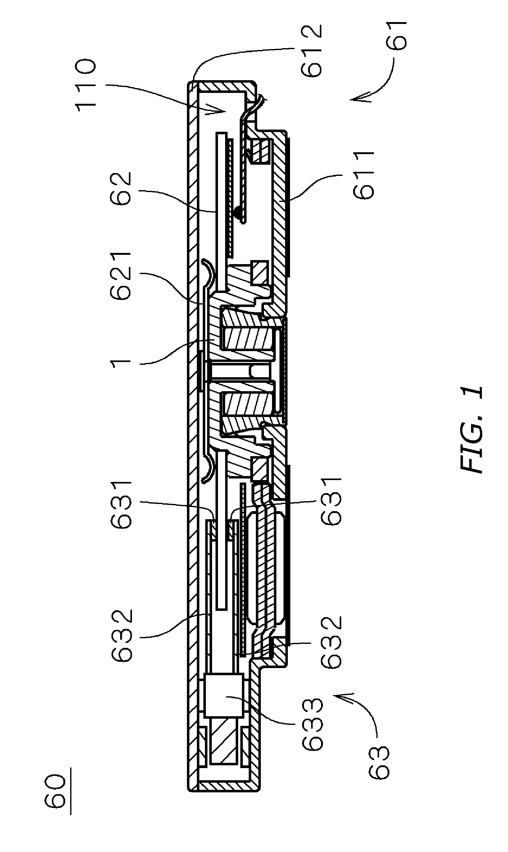
[0022]FIG. 1 shows the internal configuration of a recording disk driving device 60 including an electrically powered spindle motor 1 (hereinafter referred to as a motor 1) according to the first preferred embodiment of the present invention.

[0023] The recording disk driving device 60 is preferably a hard disk drive and includes: a recording disk 62 which has a discoid shape; an access portion 63 which read / write information from / to the recording disk 62; the motor 1 which supports and rotates the recording disk 62; and a housing 61 which accommodates the recording disk 62, access portion 63, and the motor 1 within an inside space 110.

[0024] The housing 61 includes a first housing member 611 which is a inoperculate box shape having an upper opening, to the inner bottom surface of which the motor 1 and the access portion 63 are attached, and a second housing member 612 which is a sheet shaped member occluding the upper opening of the first housing member 611 so as to define the ins...

second embodiment

[0069] A motor according to the second preferred embodiment of the present invention is described below. FIG. 6 is a plan view illustrating a core according to the second preferred embodiment of the present invention. The motor according to the second preferred embodiment of the present invention has a core 241a whose shape is different from the core 241 illustrated in FIG. 3. The rest of the configuration is the same as that of FIG. 5, and is labeled with the same reference marks in the explanation that follows.

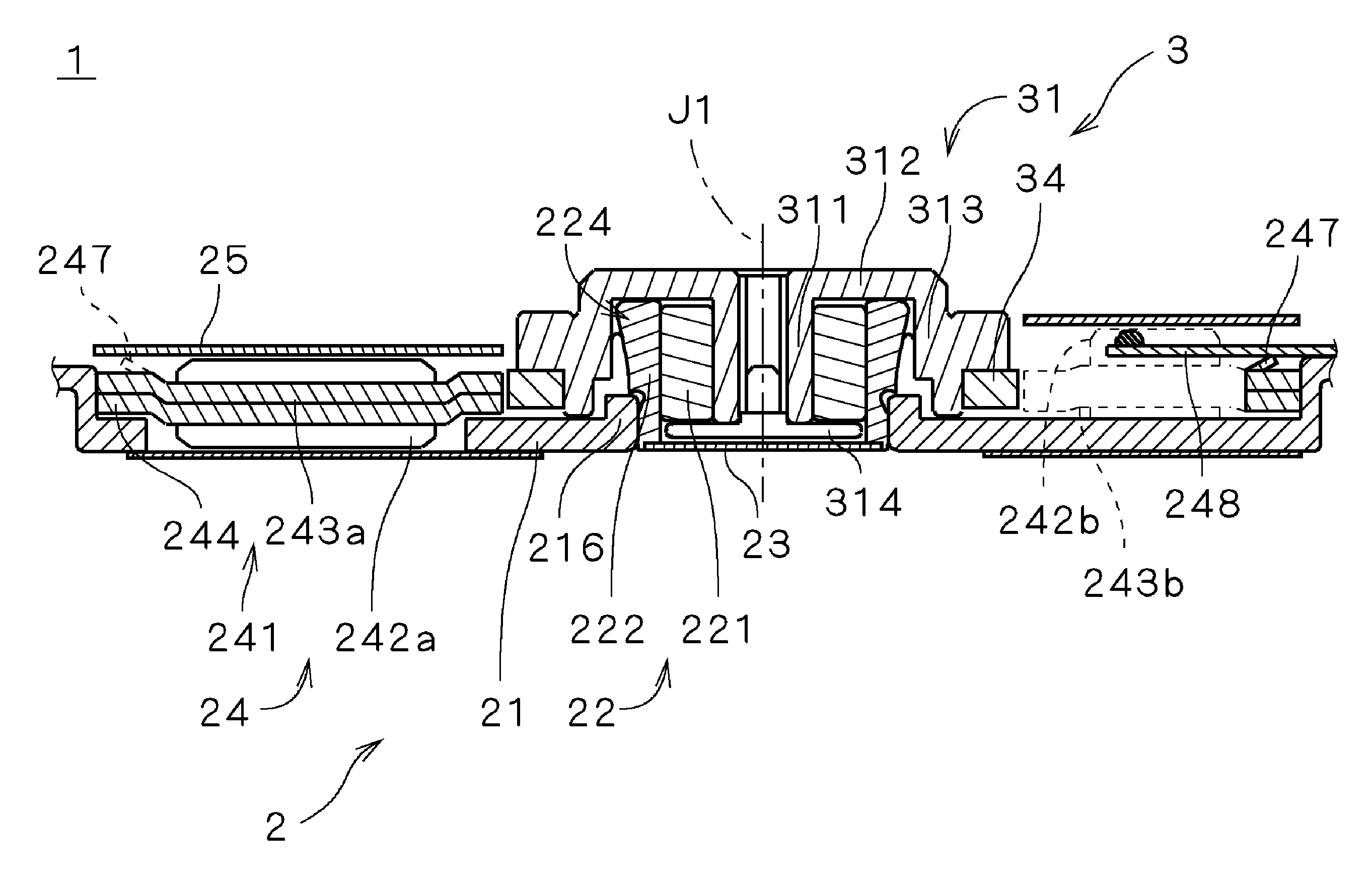
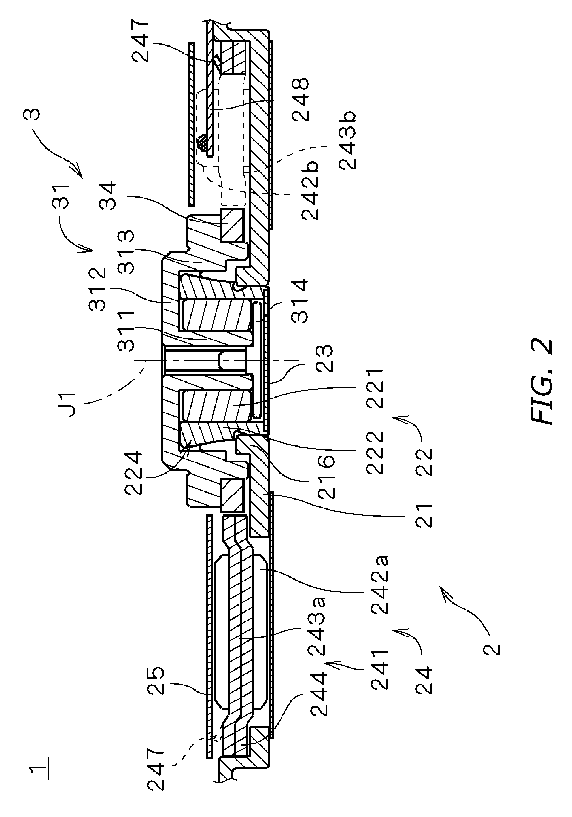
[0070] As shown in FIG. 6, the core 241a includes three first teeth 243a over which the head portion (i.e., the head 631 and the arm 632) moves and six second teeth 243b over which is out of the moving range of the head portion. The core 241a also includes the core back 244 which is a ring shape member supporting the first teeth 243a and the second teeth 243b along the outer side of the stator teeth.

[0071] The first teeth 243a and the second teeth 243b are radially arrange...


PUM


Abstract

The wire winding height of the first teeth over which the head portion moves is lower than the wire winding height of the second teeth over which is out of the moving range of the head portion. The first wire winding portion is formed so as to be radially longer than the second wire winding portion. With the configuration mentioned above, the number of winding of the wire around the first teeth (243a) is maintained without reducing the torque and varying the uniformity of the magnetic force in the circumferential direction which the stator generates.

Description

BACKGROUND OF THE INVENTION [0001] 1. Technical Field [0002] The present invention generally relates to an electric motor and a recording disk driving device including a motor, and more particularly relates to a stator for a motor. [0003] 2. Description of the Related Art [0004] Conventionally, a recording disk driving device such as a hard disk drive includes a spindle motor (hereinafter referred to as a motor) which rotates a recording disk. These days, recording disk driving devices are installed in portable music players and many other portable devices, and there is a great demand for the recording disk driving device which has more storage capacity, and reduced thickness and dimensions. Whereby, in order to make the motor thinner and smaller, it is desired to make the motor thin and small. [0005] It is known in the art that a portion of the stator of an inner rotor motor are arranged below a moving range of a magnetic head, reading / writing information from / to a recording disk, ...

Claims


Application Information

Patent Timeline
IPC IPC(8): H02K1/00
CPCH02K1/146
Inventor TAMAOKA, TAKEHITO
Owner NIDEC CORP
Learn More