Camera system with PIP in viewfinder

Inactive Publication Date: 2006-10-19
THOMSON LICENSING SA
View PDF3 Cites 5 Cited by
  • Summary
  • Abstract
  • Description
  • Claims
  • Application Information

AI Technical Summary

Benefits of technology

[0013] The ‘good-shot’ signal may also serve as an indicator to the other camera operators that they may now change positions without the risk of not covering part of the event. Even if only the ‘good-shot’ signal is transmitted, without any further signal such as video and/or audio, the risk of not covering part of the event is reduced.
[0014] In a further development of the invention, either the first or the second embodiment, the cameras may show multiple images of the respective other cameras in their viewfinder. If a ‘good-shot’ signal is received, the image coming from the camera that has issued the ‘good-shot’ signal is highlighted in the viewfinder. This allows for the other camera operators to easily identify the image which is believed to be a ‘good-shot’. Highlighting the image considered to be a ‘good-shot’ may be made in the form of a distinctive frame around the image, or by means of a blinking indicator, or other me

Problems solved by technology

When multiple cameras are used without a producer who co-ordinates the placement of the cameras, it is difficult to keep the overall-view of the production.
Firstly, talking camera operators can be very annoying if the event that is covered is, e.g., a musical and they are placed on the stage.
Secondly, when more than two camera operators try to tell each other that they have a ‘good shot’, it gets busy o

Method used


Image

  • Camera system with PIP in viewfinder
  • Camera system with PIP in viewfinder
  • Camera system with PIP in viewfinder

Examples


Example

[0023] In the figures, same or similar elements are referenced with the same reference symbol.

DETAILED DESCRIPTION OF PREFERRED EMBODIMENTS

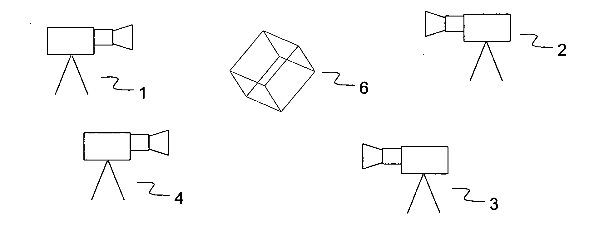
[0024] In FIG. 1 a schematic view of a typical film set is shown. Four cameras 1, 2, 3, 4 are placed around an object 6, which is to be captured. For simplification purposes, the object 6 has a cubic shaped form. The number of cameras may be larger, or there may only be two cameras involved, without leaving the scope of the invention. The cameras 1, 2, 3, 4 are taking pictures of the object 6 from different views.

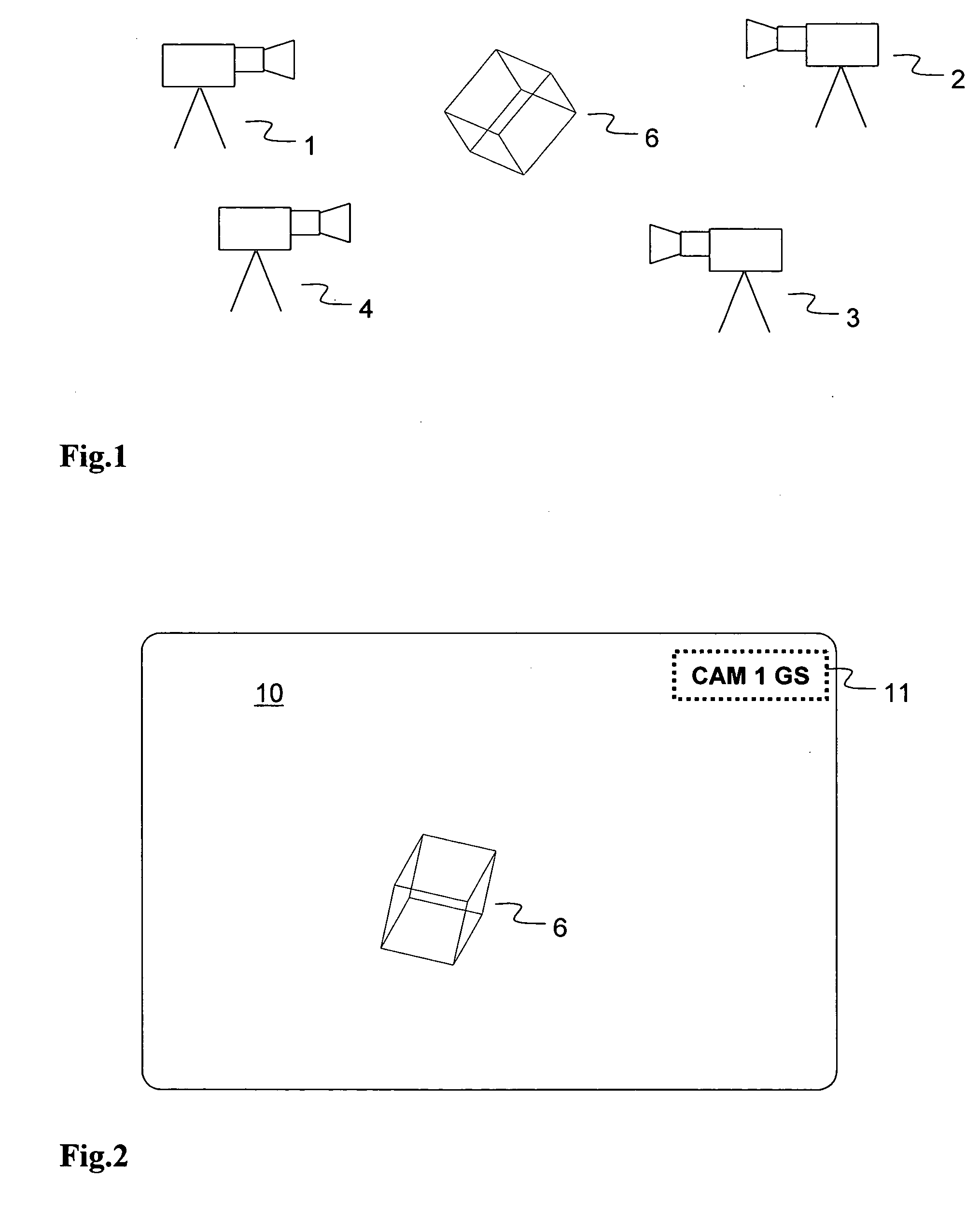
[0025] In FIG. 2 a viewfinder 10 of a camera for use in the inventive system according to a first exemplary embodiment is shown. In the viewfinder 10, the object 6 is reproduced. In the top right corner, a ‘good-shot’ indication 11 is visible. The ‘good-shot’ indication 11 is in this example a field with information about the camera number that has activated a ‘good-shot’ signal. The ‘good-shot’ indication 11 may appear in other forms...


PUM


Abstract

A system is suggested that allows for transmitting a signal from at least one first camera to a second camera, upon activation by the camera operator of the respective first camera. The signal is displayed in the viewfinder of the second camera. The signal may include an indication that the operator of the at least one first camera has a ‘good-shot’, i.e. is currently capturing images that are ready for broadcasting and/or recording. In one embodiment the signal includes an identification of the camera that transmits the signal. In another embodiment the signal includes the video signal captured from the transmitting camera. In yet another embodiment the second camera displays images coming from multiple first cameras.

Description

FIELD OF THE INVENTION [0001] The invention relates to a system in which at least two cameras are operated at the same time in one location. BACKGROUND OF THE INVENTION [0002] In the production of a video recording or a video broadcast, in which multiple cameras are used, a director or producer in a control room usually directs the camera operators with regard to the places from where they are to capture the images. The images of the individual cameras are transmitted to the control room, in which multiple monitors are placed. Each monitor shows the image coming from a different camera, and the director or producer decides to assign positions to the camera operators in order to optimise the coverage of the event that is recorded or broadcast. An image that is considered suitable for broadcast or for use in a recording that is processed after the images are captured is called a ‘good shot’. The whole content that is recorded throughout the coverage of an event is called ‘footage’. [0...

Claims


Application Information

Patent Timeline
IPC IPC(8): H04N5/232
CPCH04N5/222H04N5/45H04N5/23293H04N23/635
Inventor VAN GEEL, MARTINUS WILHELMUS CORNELISVAN DER KUIJL, EVERTKOUTSTAAL, MARCEL
Owner THOMSON LICENSING SA
Why Eureka
Try Eureka