Eureka AIR delivers breakthrough ideas for toughest innovation challenges, trusted by R&D personnel around the world.

Method for forming shoot houses

a technology of shooting houses and forming methods, applied in protective equipment, transportation and packaging, chemistry apparatus and processes, etc., can solve problems such as weakening of steel, and achieve the effects of less machining, less machining, and easy rearranging

Inactive Publication Date: 2006-10-19
ACTION TARGET ACQUISITION
View PDF98 Cites 57 Cited by
  • Summary
  • Abstract
  • Description
  • Claims
  • Application Information

AI Technical Summary

Benefits of technology

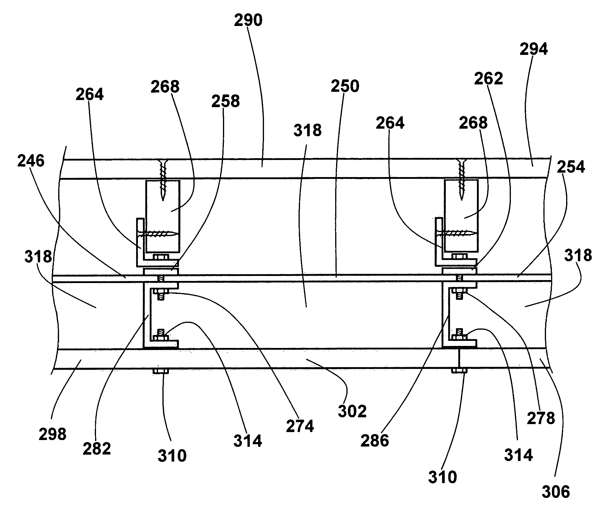
[0013] According to some aspects of the present invention, a modular ceiling may be formed as part of a modular shoot house. The ceiling may thus be formed from standard sized steel panels. The ceiling may thus be rearranged easily when changing the configuration of the shoot house and is less expensive to manufacture. Replacement plates may be obtained or constructed with less machining required.
[0015] According to other aspects of the invention, the ceiling may be relatively inexpensive. Using standard sized steel panels for the ceiling reduces the machining required to produce the ceiling parts and makes the parts easier to replace. Additionally, parts which require more machining may be formed of a milder steel.
[0017] According to yet another aspect of the invention, the ceiling may be easily configured to operate with a variety of different shoot house configurations. Because standard sized steel panels may be used in combination with standard joining and support pieces, the ceiling may easily be arranged in a number of configurations without the hassle of purchasing or acquiring many specialized pieces.

Problems solved by technology

The steel plate is then easier to replace and requires less machining of the hardened steel, which is difficult and may weaken the steel.

Method used


Image

  • Method for forming shoot houses
  • Method for forming shoot houses
  • Method for forming shoot houses

Examples


Embodiment Construction

[0046] The drawings will now be discussed in reference to the numerals provided therein so as to enable one skilled in the art to practice the present invention. The drawings and descriptions are exemplary of various aspects of the invention and are not intended to narrow the scope of the appended claims.

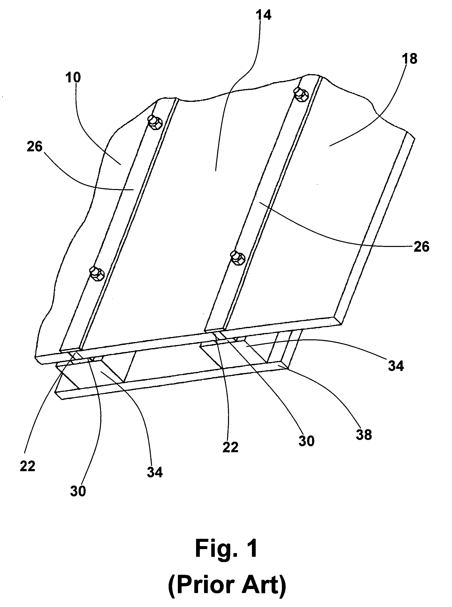
[0047] Turning to FIG. 1, a section of a modular shoot house wall as known in the prior art is shown. Modular shoot houses have been formed with bullet proof steel plate wall panels 10, 14, and 18. The joints 22 between the plates 10, 14, 18, may be covered with a backing strip of steel 26 and a facing strip of steel 30 which are bolted together to prevent bullets from passing through the joint.

[0048] Additionally, strips of wood 34 may be attached to the steel wall, with sheets of sheetrock or plywood 38 attached to the wood strips 34, forming a space to contain bullets and also making the surface of the wall look more similar to a conventional wall. Typically, a simple roof, suc...


PUM

PropertyMeasurementUnit
lengthaaaaaaaaaa
widthaaaaaaaaaa
widthaaaaaaaaaa

Abstract

A modular ballistic ceiling allows increased flexibility in building and reassembling shoot houses. Shoot houses may be built with multiple levels which are completely modular.

Description

RELATED APPLICATIONS [0001] The present application claims the benefit of U.S. Provisional Application No. 60 / 668,708, filed Apr. 5, 2005, which is incorporated herein in its entirety.BACKGROUND OF THE INVENTION [0002] 1. The Field of the Invention [0003] The present invention relates to shoot houses and ballistic training. More specifically, the present invention relates to a method for forming shoot houses with modular ballistic walls and / or a modular ballistic ceiling. [0004] 2. State of the Art [0005] In conducting training for individuals such as police officers, military personnel, etc., it is desirable to duplicate the conditions which the individual may encounter while working. Thus, training should simulate real life scenarios, with the goal of making the training as realistic as is practical. [0006] Accordingly, it is common to form shoot houses for training purposes. A shoot house is a building which is formed with bullet proof walls such that police officers, military pe...

Claims


Application Information

Patent Timeline
Patent Type & Authority Applications(United States)
IPC IPC(8): B32B15/04
CPCE04B9/00E04H9/10F41H5/24F41H5/023F41H5/013Y10T428/31678
Inventor SOVINE, H. ADDISONBATEMAN, KYLE E.BASSETT, DAVIDSOVINE, JAMES
Owner ACTION TARGET ACQUISITION
Why Eureka
Eureka Blog
Learn More