Time knob for gas and electric heater

a technology of electric heater and time knob, which is applied in the field of time knob arrangement of gas or electric heater, can solve the problems of not being suitable for all kinds of cooking, user having to spend extra money in purchasing additional equipment, and none of the above solutions are really satisfactory

Inactive Publication Date: 2006-10-19
YU SHIH SZU +1
View PDF5 Cites 35 Cited by
  • Summary
  • Abstract
  • Description
  • Claims
  • Application Information

AI Technical Summary

Benefits of technology

[0009] A main object of the present invention is to provide a time knob arrangement for a gas or an electric heater which is capable of automatically shutting off after a predetermined period of time. In other words, the user is able to pre-set a time schedule for a gas or electric heater.

Problems solved by technology

One inherent problem for this kind of conventional gas heater is that once it has been turned on, it will still be on until the user manually turns it off by rotating the actuation button in a predetermined direction.
The implication of this solution is of course, to phrase out the traditional gas heaters, which may not be suitable for all kinds of cooking.
Second, people may simply buy other equipments which provide automatic on-off control for extended cooking.
Obviously, the user has to spend extra money in purchasing additional equipments for specific cooking purposes.
One may appreciate that none of the above solutions are really satisfactory.
Moreover, as a matter of fact, some of these equipments are expensive.

Method used


Image

  • Time knob for gas and electric heater
  • Time knob for gas and electric heater
  • Time knob for gas and electric heater

Examples


Embodiment Construction

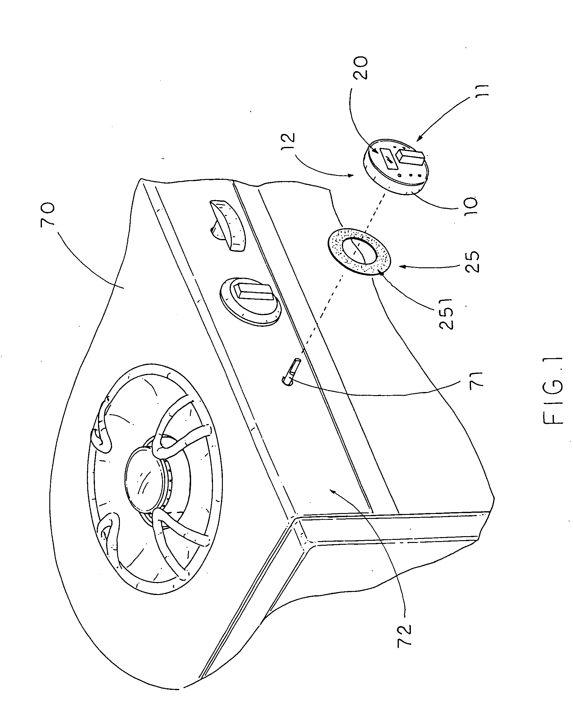
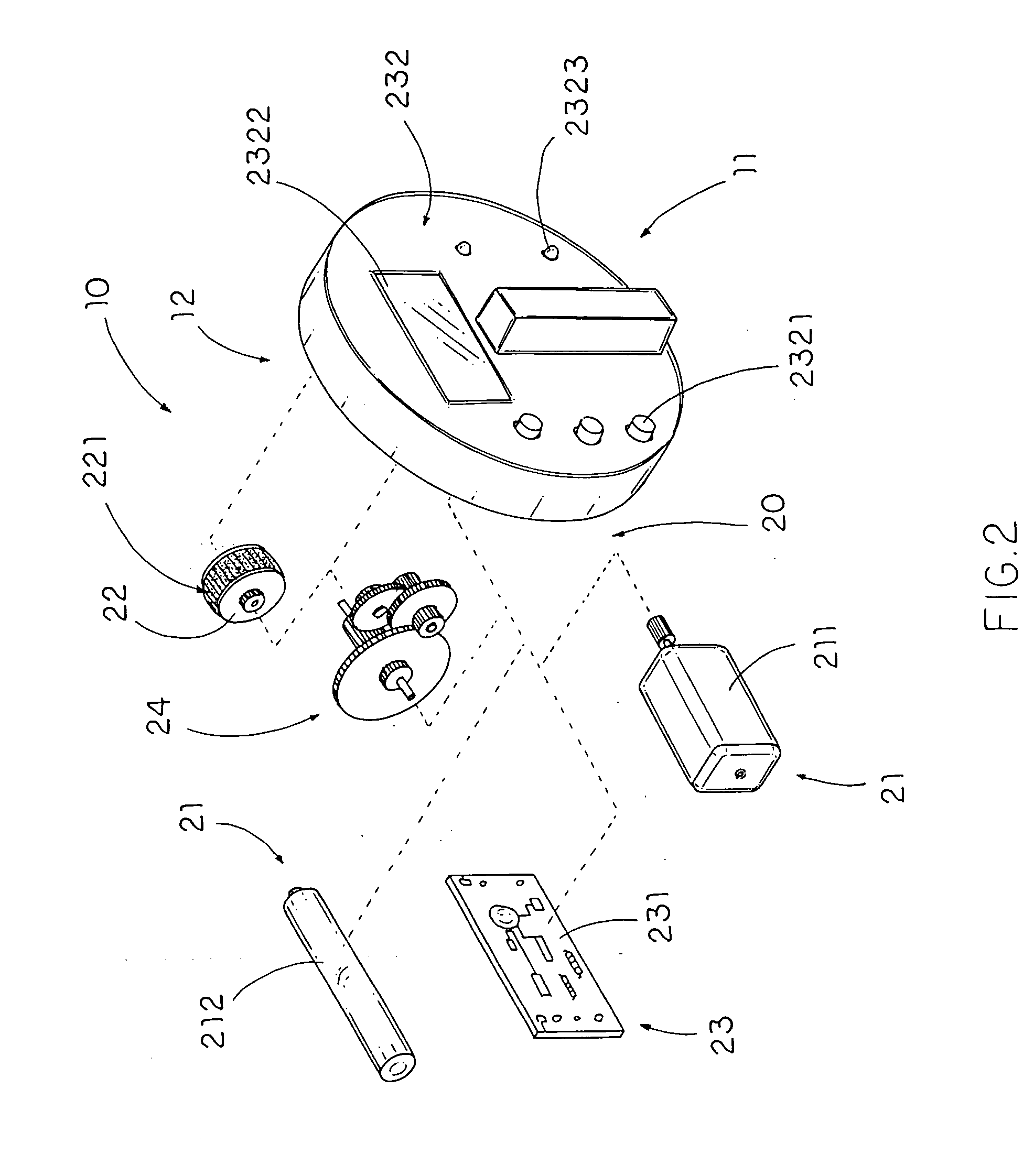
[0024] Referring to FIG. 1, FIG. 2 and FIG. 4 of the drawings, a timer knob arrangement for a heater 70, such as a gas-operated heater, is illustrated. The heater 70 comprises a main casing having an operation surface 72, and a stove unit supported by the main casing, wherein the stove unit comprises an operation pin 71 rotatably extended from the operation surface 72, and adapted to generate controlled fire by gas. According to a preferred embodiment of the present invention, the timer knob arrangement comprises an ignition button 10, and a timer control 20.

[0025] The ignition button 10 has an actuation side 11, an opposed engaging side 12 defining a receiving cavity 13 therebetween, and a pin holder provided at the engaging side 12 for substantially engaging with the operation pin 71 that the engaging side 12 is facing towards the operation surface 72 of the heater 70, wherein the ignition button 10 is rotatably switched between a switched off position and an operation position w...


PUM


Abstract

A timer knob arrangement for a heater includes an ignition button and a timer control. The ignition button is rotatably switched between a switched off position and an operation position with respect to an operation pin of the heater. The timer control includes a power unit, a runner wheel driven by the power unit and is rotatably supported by the ignition button at a position tangentially with respect to the operation pin, and a time control unit. When the time control unit is activated to actuate the power unit, the runner wheel is driven to rotate and to run on the operation surface, so as to drive the ignition button turning back to the switched off position for ensuring a flow of gas being shut off from the heater.

Description

BACKGROUND OF THE PRESENT INVENTION [0001] 1. Field of Invention [0002] The present invention relates to a heater, and more particularly to a time knob arrangement for a gas or an electric heater which is capable of automatically shutting off an ignition button after a predetermined period of time. [0003] 2. Description of Related Arts [0004] A conventional heater, such as a domestic gas heater for use in kitchen, usually comprises a housing, a heater unit provided on the housing for controllably generating fire, and an actuation unit operatively provided on the housing to communicate with the heater unit for selectively turning the heater unit on and off. The heater unit usually comprises an operation pin rotatably extended from the housing, wherein the actuation unit, which is usually embodied as an actuation button, is rotatably engaged with the operation pin for rotating the operation pin to turn on or turn off the heater unit. [0005] One inherent problem for this kind of conven...

Claims


Application Information

Patent Timeline
Patent Type & Authority Applications(United States)
IPC IPC(8): F23N5/00
CPCF23N5/22F24C3/124F23N2027/28F23N2227/28
Inventor YU, SHIH-SZUCHENG, STEPHEN
Owner YU SHIH SZU
Why Eureka
Try Eureka