[0025] The particular values and configurations discussed in these non-limiting examples can be varied and are cited merely to illustrate at least one embodiment and are not intended to limit the scope thereof.
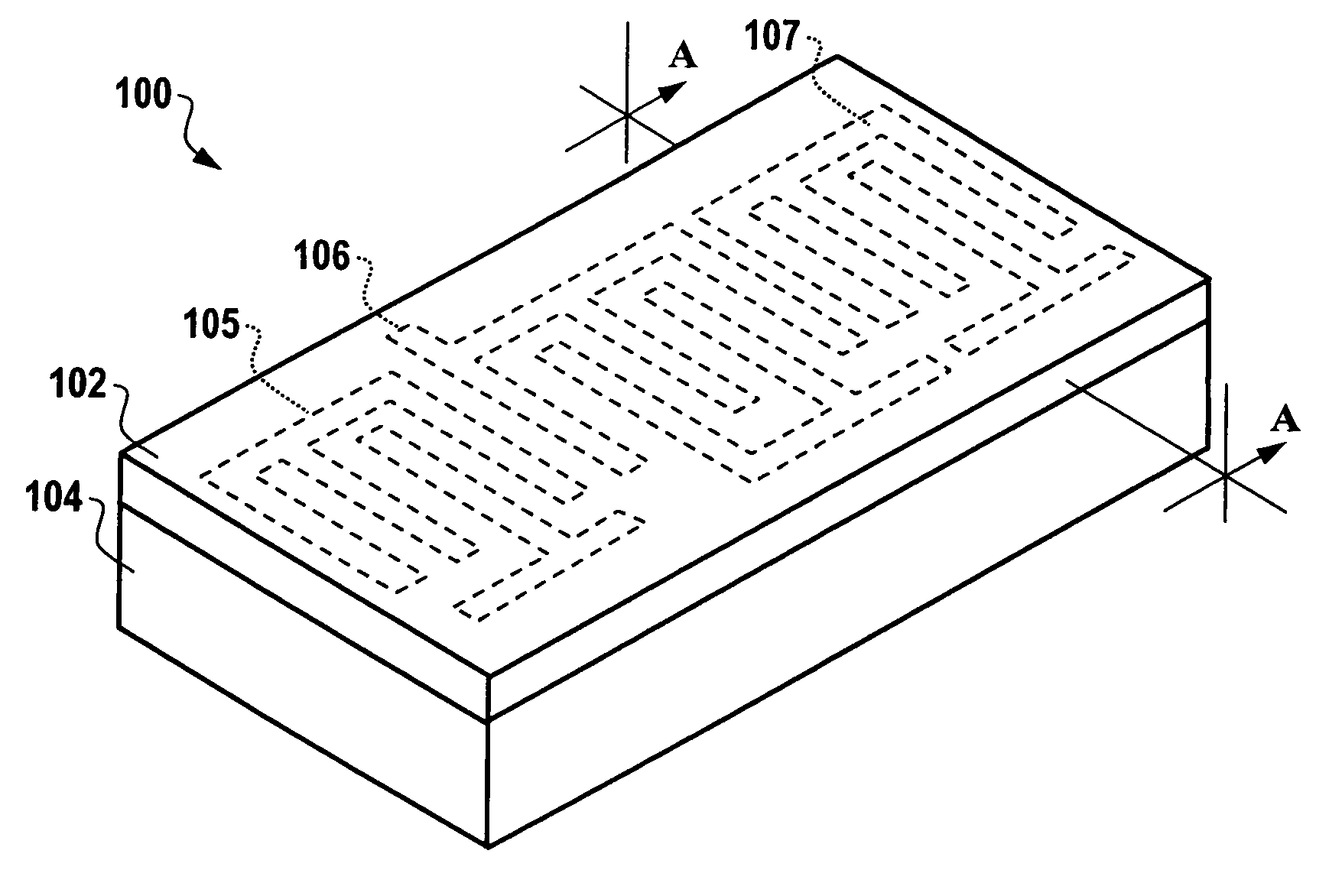
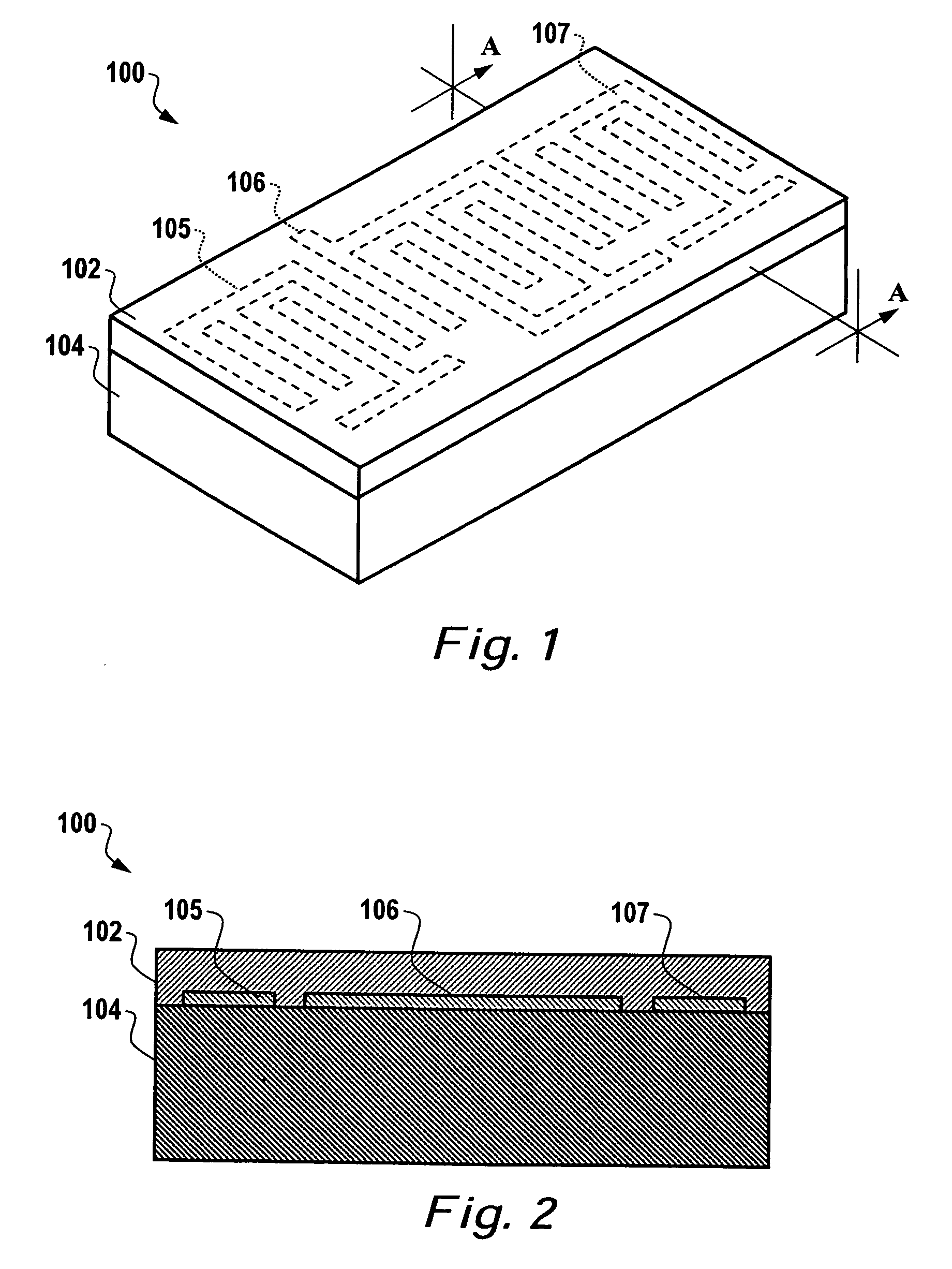
[0026]FIG. 1 illustrates a perspective view of an acoustic wave device 100, which can be implemented in accordance with one embodiment. Acoustic wave device 100 generally includes one or more interdigital transducers (IDT) 105, 106, 107, which can be formed on a substrate 104, which may be formed from an elastic substrate material. Substrate 104 is preferably formed from a piezoelectric material. The acoustic wave device 100 can be implemented in the context of a sensor chip. Interdigital transducers 105, 106, 107 can be configured in the form of electrodes or resonators, depending upon design considerations.
[0027] Note that the acoustic wave device 100 represents only one type of acoustic wave device that can be adapted for use with the embodiments disclosed herein. It can be appreciated that a variety of other types (e.g., SH-SAW, BAW, APM, SH-APM, FPW, SH-SAW-DL, SH-SAW-R, etc.) can be utilized in accordance with the embodiments described herein. Additionally, acoustic wave device 100 can be implemented in a variety of shapes and sizes.
[0028]FIG. 2 illustrates a cross-sectional view along line A-A of the acoustic wave device 100 depicted in FIG. 1, in accordance with one embodiment of the present invention. Piezoelectric substrate 104 can be formed from a variety of substrate materials, such as, for example, quartz, lithium niobate (LiNbO3), lithium tantalite (LiTaO3), Li2B4O7, GaPO4, langasite (La3Ga5SiO14), ZnO, and/or epitaxially grown nitrides such as Al, Ga or Ln, to name a few. Interdigital transducers 105, 106, 107 can be formed from materials, which are generally divided into three groups. First, interdigital transducers 105, 106, 107 can be formed from a metal group material (e.g., Al, Pt, Au, Rh, Ir Cu, Ti, W, Cr, or Ni). Second, interdigital transducers 105, 106, 107 can be formed from alloys such as NiCr or CuAl. Third, interdigital transducers 105, 106, 107 can be formed from metal-nonmetal compounds (e.g., ceramic electrodes based on TiN, CoSi2, or WC).
[0029] The coating 102 need not cover the entire planar surface of the piezoelectric substrate 104, but can cover only a portion thereof, depending upon design constraints. Coating 102 can function as a guiding layer. Selective coating 102 can cover interdigital transducers 105, 106, 107 and the entire planar surface of piezoelectric substrate 104. Because acoustic wave device 100 functions as a multiple mode sensing device, excited multiple modes thereof generally occupy the same volume of piezoelectric material. Multiple modes excitation allows separations of temperature change effects from pressure change effects. The multi-mode response can be represented by multiple mode equations, which can be solved to separate the response due to the temperature and pressure.
[0030]FIG. 3 illustrates a perspective view of an acoustic wave device 300, which can be implemented in accordance with an embodiment. The configuration depicted in FIGS. 3-4 is similar to that illustrated in FIGS. 1-2, with the addition of an antenna 308, which is connected to and disposed above a wireless excitation component 310 (i.e., shown in FIG. 4). Acoustic wave device 300 generally includes interdigital transducers 305, 306, 307 formed on a piezoelectric substrate 304.
[0031] Acoustic wave device 300 can therefore function as an interdigital surface wave device, and one, in particular, which utilizing surface-skimming bulk wave techniques. Interdigital transducers 305, 306, 307 can be configured in the form of an electrode. A coating 302 can be selected such that a particular species to be measured is absorbed by the coating 302, thereby altering the acoustic properties of the acoustic wave device 300. Various selective coatings can be utilized to implement coating 302.
[0032] A change in acoustic properties can be detected and utilized to identify or detect the substance or species absorbed and/or adsorbed by the coating 302. Thus, coating 302 can be excited via wireless means to implement a surface acoustical model. Thus, antenna 308 and wireless excitation component 310 can be utilized to excite multiple modes, thereby allowing separation of temperature change effects from pressure change effects. Such an excitation can produce a variety of other modes of acoustic wave device 300.
[0033]FIG. 4 illustrates a cross-sectional view along line A-A of the acoustic wave device 300 depicted in FIG. 3, in accordance with one embodiment of the present invention. Thus, antenna 308 is shown in FIG. 4 disposed above coating 302 and connected to wireless excitation component 310, which can be formed within an area of coating 302. Similar to the configuration of FIG. 2, Piezoelectric substrate 304 can be formed from a variety of substrate materials, such as, for example, quartz, lithium niobate (LiNbO3), lithium tantalite (LiTaO3), Li2B4O7, GaPO4, langasite (La3Ga5SiO14), ZnO, and/or epitaxially grown nitrides such as Al, Ga or Ln, to name a few.
[0034] Interdigital transducers 305, 306, 307 can be formed from materials, which are generally divided into three groups. First, interdigital transducer 106 can be formed from a metal group material (e.g., Al, Pt, Au, Rh, Ir Cu, Ti, W, Cr, or Ni). Second, interdigital transducers 305, 306, 307 can be formed from alloys such as NiCr or CuAl. Third, interdigital transducers 305, 306, 307 can be formed from metal-nonmetal compounds (e.g., ceramic electrodes based on TiN, CoSi2, or WC). Thus, the electrode formed from interdigital transducer can comprise a material formed from at least one of the following types of material groups: metals, alloys, or metal-nonmetal compounds.
[0035]FIG. 5 illustrates a graph 500 depicting the Coriolis force acting on particle vibrations in a standing wave 501 in accordance with a preferred embodiment. In graph 500, the rotating direction is indicated generally by curved arrow 508 relative to the x-y-z axes. The Coriolis force is represented in graph 500 by arrow 500, while the vibration velocity 502 is indicated by the value T. Note that as utilized herein, the term “Coriolis force” generally refers to the Coriolis force or Coriolis effect, which is the inertial force associated with a change in the tangential component of a particle's velocity. The Coriolis force generally acts on moving objects when observed in a frame of reference which is itself rotating. Because of the rotation of the observer, a freely moving object does not appear to move steadily in a straight line as usual, but rather as if, besides an outward centrifugal force, a “Coriolis force” acts on it, perpendicular to its motion, with a strength proportional to its mass, its velocity and the rate of rotation of the frame of reference.
[0036]FIG. 6 illustrates a top view of a passive and wireless acoustic wave (e.g., SAW and/or tuning fork) rotation rate sensor 600 that can be implemented in accordance with a preferred embodiment. Sensor 600 generally functions as a rotation rate sensing apparatus in the form of a surface acoustic wave device that includes a plurality of interdigital transducers 605, 606, and 607 configured upon an elastic substrate 604, which may be formed from a piezoelectric material. Note that substrate 604 is analogous to substrates 104, 103 depicted in FIGS. 1-4 herein. Interdigital transducer 605 generally functions as a first interdigital transducer, while interdigital transducer 606 comprises a second interdigital transducer and interdigital transducer 607 comprises a third interdigital transducer in the context of three IDT system. Sensor 600 generally functions as a rotation rate sensing apparatus in the form of a tuning fork device as illustrated in further detail herein with respect to FIG. 8
[0037] First and third interdigital transducers 605 and 607 respectively form generator resonators that can generate a standing wave (e.g., see wave 501 in FIG. 5) subject to the Coriolis force (e.g., see arrow 504 in FIG. 5) by adding two progressive waves at each of the first and third respective interdigital transducers 605, 607. The second interdigital transducer 606 forms a sensor that is also configured upon the elastic substrate 604 in order to excite an electric field at the second interdigital transducer or sensor 606 in order to detect the amplitude of the electric field. The amplitude thereof is proportional to the magnitude of the Coriolis force and provides an indication of angular rate data thereof. Additionally, an antenna 608 can be formed on the substrate 604 for the transmission of angular or rotation rate data.
[0038] The design of the passive and wireless SAW rotation rate sensor 600 is such that three SAW resonators 605, 606, 607 can be implemented as indicated in FIG. 6. The two SAW resonators or interdigital transducers 605, 607 function as a generator, and SAW resonator or interdigital transducer 606 functions as a sensor or sensor resonator. The standing wave 501 indicated in FIG. 5 can be generated utilizing two progressive waves generated at each generator resonator 605, 607. The sensor resonator 606 is located at the center of the two generator resonators 605, 607. When the substrate 604 is rotated in the right direction, an electric field is excited at the sensor resonator 606. The amplitude of this electric field is proportional to the magnitude of the Coriolis force depicted at arrow 504 in graph 500 of FIG. 5. The Coriolis force thus excites the electric field between electrodes. Note that the interdigital transducers 605, 606, 607 can be implemented in the context of one or more of the following: a filter, a resonator a plurality of delay lines.
[0039]FIG. 7 illustrates a wireless and passive SAW rotation rate sensing system 700 that can be implemented in accordance with a preferred embodiment. Note that in FIGS. 6-7, identical or similar parts are indicated by identical reference numerals. System 700 generally includes the passive and wireless SAW rotation rate sensor 600 depicted in FIG. 6. The passive and wireless SAW rotation rate sensor 600 can be located or associated with a rotating object 701. Rotation of the object 701 is indicated by arrows 712, 714. Wireless data can be transmitted from and to the passive and wireless SAW rotation rate sensor 600 via antenna 608 by an interrogation electronics (ID) and transmitter/receiver unit 710, which is associated with an antenna 708.
[0040]FIG. 8 illustrates a wireless and passive tuning fork rotation rate sensing device 800 that can be implemented in accordance with the passive and wireless acoustic wave rotation rate sensor 600 depicted in FIG. 6-7. The tuning fork rotation rate sensing device 800 can be adapted for use with the passive and wireless tuning fork rotation rate sensor 600 depicted in FIGS. 6-7. Note that in FIGS. 6-8, identical or similar parts are indicated by identical reference numerals. Note that other configurations can also be adapted for use in accordance with varying embodiments.
[0041] As indicated earlier, the passive and wireless acoustic wave rotation rate sensor 600 can be located on or associated with the rotating object 701. Rotation of the object 701 is indicated by arrows 712, 714. Wireless data can be transmitted from and to the passive and wireless tuning fork rotation rate device 600 via antennas 806 and 808 by an interrogation electronics (ID) and transmitter/receiver unit 710, which is associated with an antenna 708. Note that antennas 806, 800 indicated in FIG. 8 can be implemented in place or in association with antenna 608 depicted in FIG. 7. In general, the wireless and passive tuning fork rotating rate sensing device 800 can be configured upon substrate 604.
[0042] Primary tuning fork electrode, for example, can be shaped in the context of “drive tines” or a drive electrode, as indicated in FIG. 8. Similarly, secondary tuning fork electrode can be shaped in the context of “pickup tines” or a pickup electrode, as also indicated in FIG. 8. The first antenna 806 can be associated with the drive electrode 605, while the second antenna 808 can be associated with the pickup electrode 607.
[0043]FIG. 9 illustrates basic mode shapes 900 of an “H” shape tuning fork rotation rate sensing device that can be implemented in accordance with varying embodiments. The shapes 900 are generally divided into a number of varying shapes 902-918 as indicated in FIG. 9. By utilizing the H-Shaped tuning fork configurations depicted in FIG. 9, and adapting such configurations to the sensor depicted in FIG. 6-8, a sensor can be formed that includes an elastic substrate rotatable in a first direction in order to excite an electric field at the sensor in order to detect an amplitude of the electric field, wherein the amplitude, which is proportional to the magnitude of the Coriolis force, provides an indication of angular rate data thereof. In the vibration beams configuration, drive beam(s) and pickup beam(s) can be utilized. The vibration beams are excited through RF signal and Coriolis force will excite the pickup beam(s) to get the rotation rate data.
[0044] The H-shaped tuning fork configurations depicted in FIG. 9 represent merely one type of angular sensing configuration that can be adapted for use in accordance with one or more embodiments. Other configurations are possible. An example of one type of configuration that can be adapted for use in accordance with one particular embodiment is disclosed in non-limiting U.S. Pat. No. 6,151,965, entitled “Structure of Angular Rate Sensor for Minimizing Output Noise,” which issued to Takehiro Watarai on Nov. 8, 2000. U.S. Pat. No. 6,151,965 is incorporated herein by reference.
[0045] It will be appreciated that variations of the above-disclosed and other features and functions, or alternatives thereof, may be desirably combined into many other different systems or applications. Also that various presently unforeseen or unanticipated alternatives, modifications, variations or improvements therein may be subsequently made by those skilled in the art which are also intended to be encompassed by the following claims.