Cable tie with fir-tree type fastener

a technology of fir branches and fasteners, applied in the field of tie, can solve the problems of high undesirable and injury to workers, and achieve the effect of convenient use and inexpensive manufacturing

Inactive Publication Date: 2006-10-26
AVERY DENNISON CORP
View PDF58 Cites 27 Cited by
  • Summary
  • Abstract
  • Description
  • Claims
  • Application Information

AI Technical Summary

Benefits of technology

[0021] It is yet still another object of the present invention to provide a cable tie of the type as described above which includes a limited number of parts, which is easy to use and which is inexpensive to manufacture.

Problems solved by technology

As can be appreciated, the above-described flute interference condition serves to significantly increase the insertion force associated with fastener 11, which is highly undesirable.
In an assembly line environment (e.g., in an automotive manufacturing facility), the relatively high insertion force required for such a fastener can result in, among other things, injury to its workers (e.g., carpal tunnel syndrome), which is highly undesirable.

Method used


Image

  • Cable tie with fir-tree type fastener
  • Cable tie with fir-tree type fastener
  • Cable tie with fir-tree type fastener

Examples


Embodiment Construction

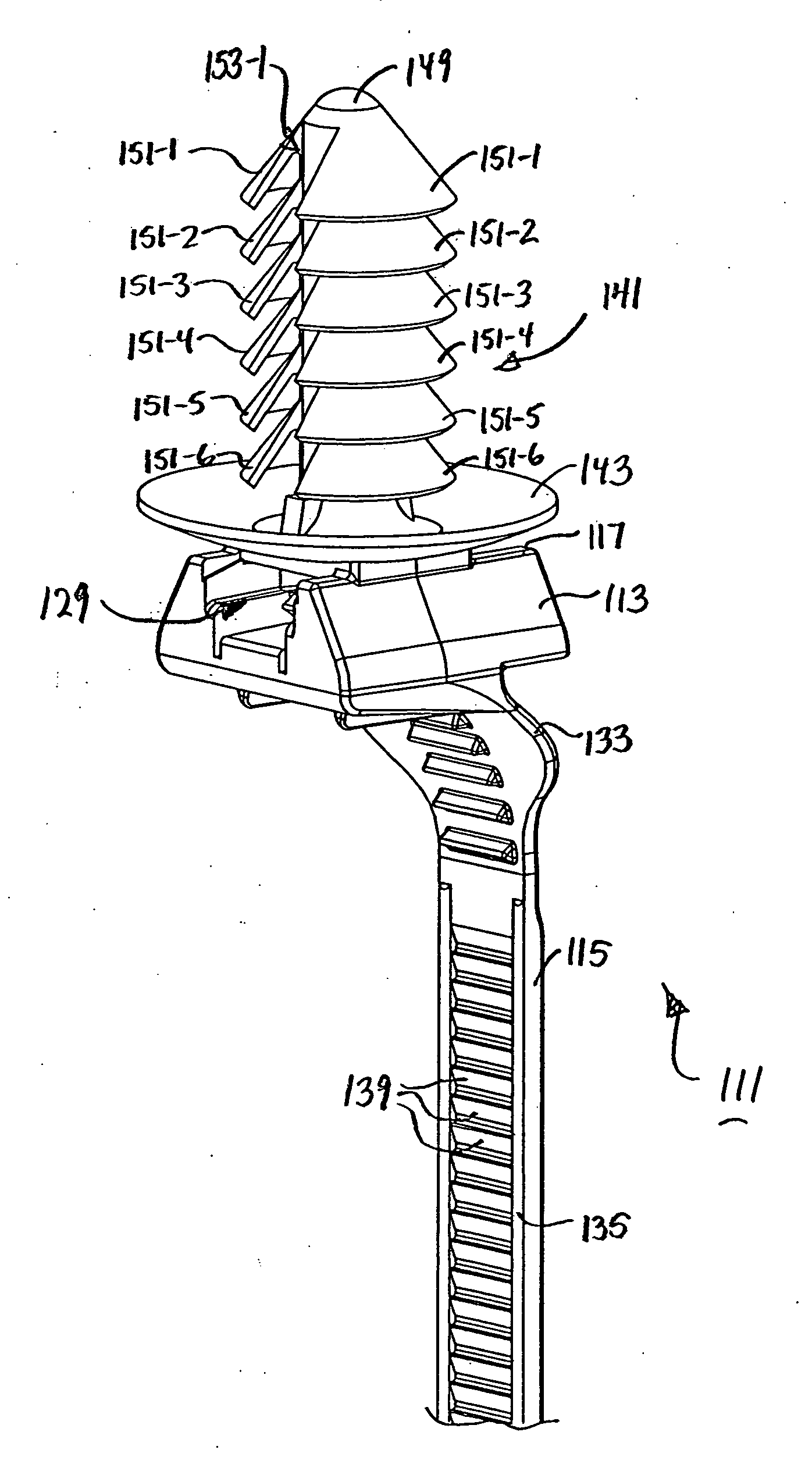
[0035] Referring now to FIGS. 2-5, there is shown a cable tie (also referred to herein simply as a tie) which is constructed according to the teachings of the present invention, the tie being identified generally as reference numeral 111. As one of its potential applications, tie 111 can be used to bundle together a group of wires and, in turn, retain said bundle against an automotive panel.

[0036] Cable tie 111 comprises a locking head 113 and an attached strap 115. Preferably, tie 111 is manufactured of a plastic material, such as nylon, and is formed as a single piece using conventional molding techniques.

[0037] Locking head 113 is generally rectangular in shape and comprises a top wall 117, a bottom wall 119, a front wall 121, a rear wall 123, a first side wall 125 and a second side wall 127. Together, top wall 117, bottom wall 119, front wall 121, rear wall 123, first side wall 125 and second side wall 127 define a strap accepting channel 129 which extends longitudinally throu...


PUM


Abstract

A one-piece cable tie includes a locking head and an attached strap, the locking head being adapted to receive and selectively engage a portion of the strap when the tie is formed into a closed loop. The cable tie additionally includes a fir-tree fastener formed onto the locking head, the fastener being sized and shaped to be fittingly inserted through a quarter-inch circular opening in a panel. The fastener includes a stem and a plurality of flutes formed onto the stem in such a manner so as not to interfere with one another when the fastener is being fittingly inserted through the opening in the panel. Because the fastener does not experience flute interference when inserted through a panel opening, the fastener is characterized as having a relatively low insertion force (i.e., the force required to insert the fastener into the panel opening) while maintaining a relatively high extraction force (i.e., the force required to withdraw the fastener from the panel opening).

Description

CROSS-REFERENCE TO RELATED APPLICATIONS [0001] The present application claims the benefit under 35 U.S.C. 119(e) of U.S. provisional Patent Application Ser. No. 60 / 673,221, filed Apr. 20, 2005, the disclosure of which is incorporated herein by reference.BACKGROUND OF THE INVENTION [0002] The present invention relates generally to ties and, more particularly, to ties which can be formed into a closed loop. [0003] Ties are well known in the art and are widely used in a variety of different applications. [0004] One tie which is well known and widely used in the art is the cable tie. Cable ties are commonly used in commerce to bundle together of a plurality of objects, such as a group of parallel wires. [0005] One type of cable tie which is well known in the art comprises a serrated strap which is fitted to an apertured head. In use, the cable tie can be formed into closed loop by inserting the serrated strap through the apertured head. With the serrated strap inserted through the apert...

Claims


Application Information

Patent Timeline
Patent Type & Authority Applications(United States)
IPC IPC(8): F16M13/00F16L3/12
CPCF16B21/084H02G3/32H02G3/26F16L3/2336
Inventor FRANKS, JOHN R.
Owner AVERY DENNISON CORP
Why Eureka
Try Eureka