Multiplex microparticle system
- Summary
- Abstract
- Description
- Claims
- Application Information
AI Technical Summary
Benefits of technology
Problems solved by technology
Method used
Image
Examples
example 1
Preparation a Microparticle Array
[0055] This example describes preferred methods for preparing a microparticle array for use in flow cytometry.
[0056] The array described herein is intended for use in a detection assay in which the microparticles are coated with an analyte-specific reagent, and a labeled-reporter reagents are used to measure the amount of analyte bound to a microparticle. To maximize sensitivity of the detection assay, it is desirable to label the reporter reagents with a particularly bright fluorophore, preferably phycoerythrin (PE), which has an emission maximum at 578 nm. Thus, the array is prepared assuming that an appropriate detection channel is reserved for measuring the PE-labeled reporter reagents.
1. Detection Channels
[0057] The detection channels used to measure the microparticle fluorescence are selected from the channels available using a flow cytometer. Preferred flow cytometers are the BD FACSCalibur™ flow cytometer and the BD FACSArray™ flow cytom...
example 2
29-Population Array
[0079] Bead subsets were prepared essentially as described in Example 1 using each of the dyes listed in the table, below. All dyes were obtained from Exciton (Dayton, Ohio). Excitation and emission maxima, which were measured in either ethanol, methanol, or dichloromethane, are known to be somewhat dependent on the solvent used for the measurements, and slightly different results may be obtained using different solvents.
DyeExcitation MaxEmission MaxPopulations used in arrayLD7006476737LDS7306146954LDS7505727043LDS7515427001Oxazine 7256456766ABS6436406558
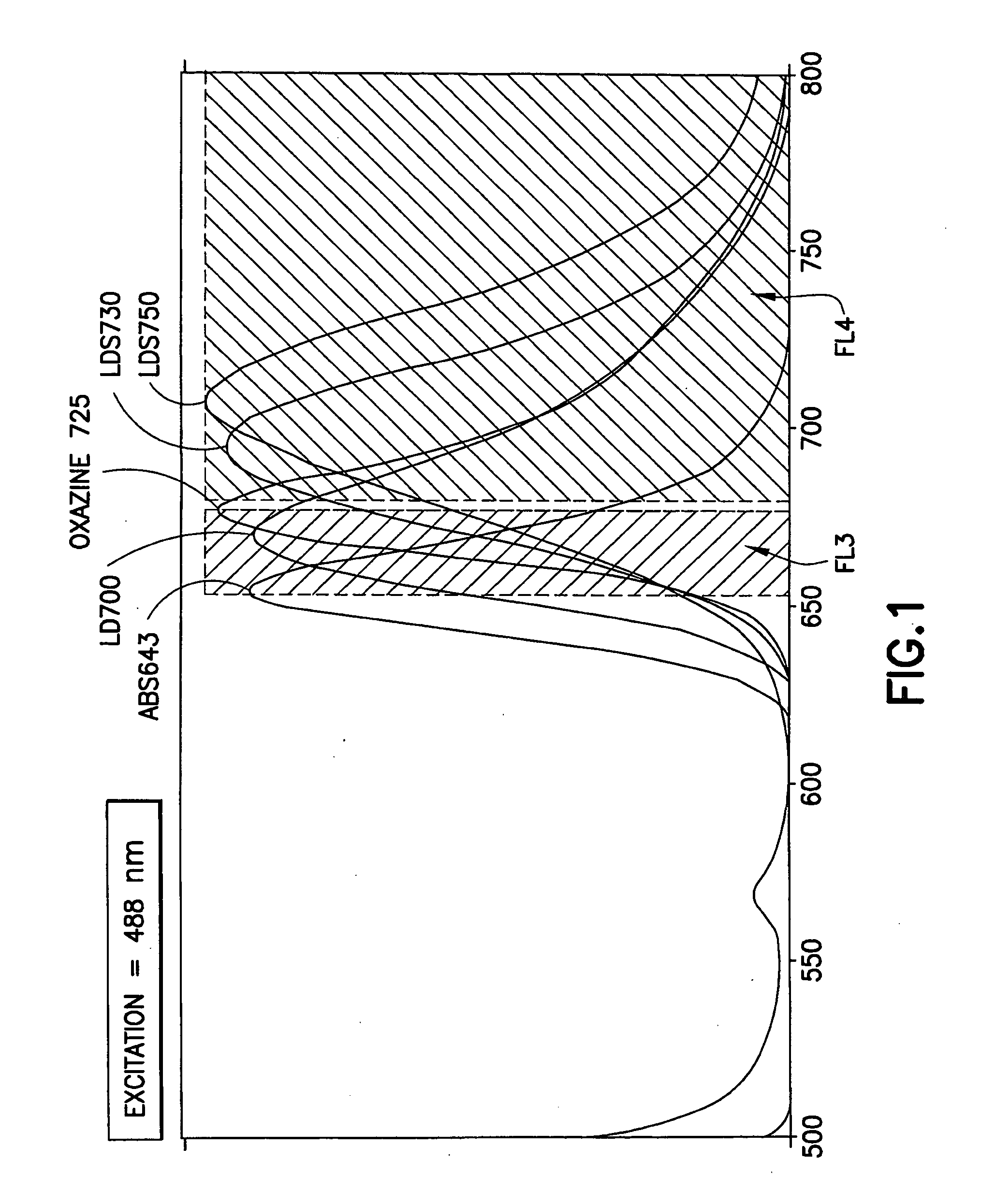
[0080] The emission spectra of these dyes (with the exception of LDS751) are shown in FIG. 1. Also shown are the boundaries of the detection channel defined using a BD FACSArray flow cytometer.
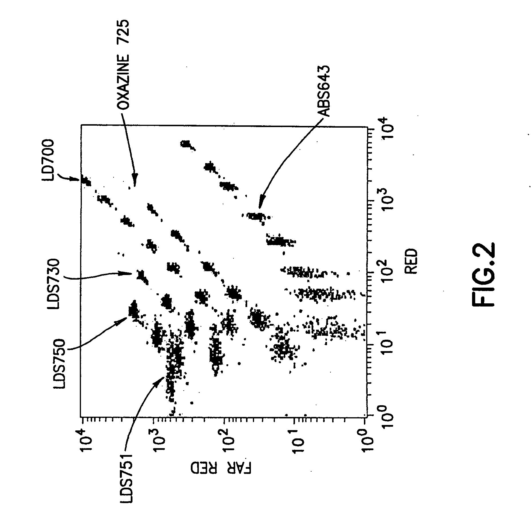
[0081] Sets of dyed beads, each containing bead populations dyed with different amounts of one of the dyes, were combined and were analyzed on a BD FACSArray flow cytometer, as described above. Bead populations that were...
example 3
Extended Array
[0083] The bead array described in Example 2 was incrementally extended by the inclusion of a bead set dyed using LDS765 (Exciton, Dayton, Ohio), prepared essentially as described above. The measured excitation and emission maxima for the dye are shown in the table, below:
DyeExcitation MaxEmission MaxPopulations used in arrayLD7655957523
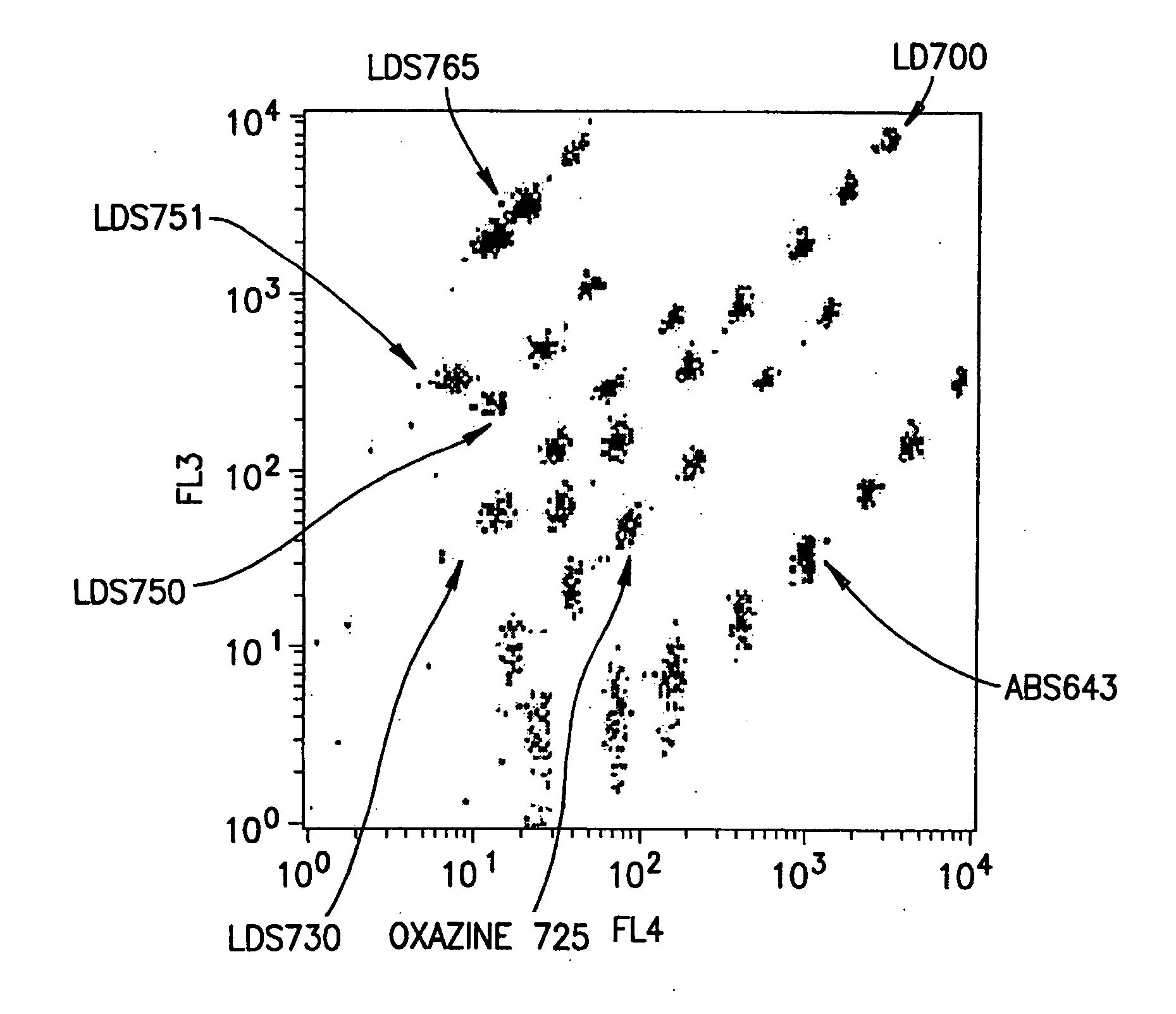
[0084] For this analysis, the sets of dyed beads, were analyzed on a BD FACSCalibur flow cytometer, as described above. Bead populations from the set dyed with LDS765 were selected such that the populations were both uniquely distinguishable and simultaneously on-scale relative to the bead populations in the previously constructed array. Three populations could be added to the 29-population array. FIG. 3 shows a dot-plot (FL3×FL4) of the selected bead array containing 32 distinguishable bead populations.
[0085] The emissions of the bead populations in the PE-channel (FL2) also were measured (results not shown), and minimal spillover ...
PUM
| Property | Measurement | Unit |
|---|---|---|
| Volume | aaaaa | aaaaa |
| Volume | aaaaa | aaaaa |
| Volume | aaaaa | aaaaa |
Abstract
Description
Claims
Application Information
 - R&D Engineer
- R&D Manager
- IP Professional
- Industry Leading Data Capabilities
- Powerful AI technology
- Patent DNA Extraction
Browse by: Latest US Patents, China's latest patents, Technical Efficacy Thesaurus, Application Domain, Technology Topic.
© 2024 PatSnap. All rights reserved.Legal|Privacy policy|Modern Slavery Act Transparency Statement|Sitemap


