
Fixing device for a centrifuge rotor cover

Active Publication Date: 2006-10-26
THERMO ELECTRONICS LED GMBH
View PDF3 Cites 13 Cited by
  • Summary
  • Abstract
  • Description
  • Claims
  • Application Information

AI Technical Summary

Benefits of technology

[0006] It is therefore an object of the present invention to provide a fixing device for a cover, using which a receiving chamber of a centrifuge rotor for receiving samples to be centrifuged, which is driven using a drive unit, may be closed aerosol-tight, so that the cover may be mounted or dismounted one-handed and it is simultaneously possible to remove the rotor from the centrifuge without loosening or removing the cover of the centrifuge rotor.

Problems solved by technology

A disadvantage of these achievements of the object is that such fixing is only possible using both hands and is therefore viewed as complex.
This is disadvantageous, since a receiving chamber of the centrifuge rotor which is possibly closed aerosol-tight must thus be opened.

Method used


Image

  • Fixing device for a centrifuge rotor cover
  • Fixing device for a centrifuge rotor cover
  • Fixing device for a centrifuge rotor cover

Examples


Embodiment Construction

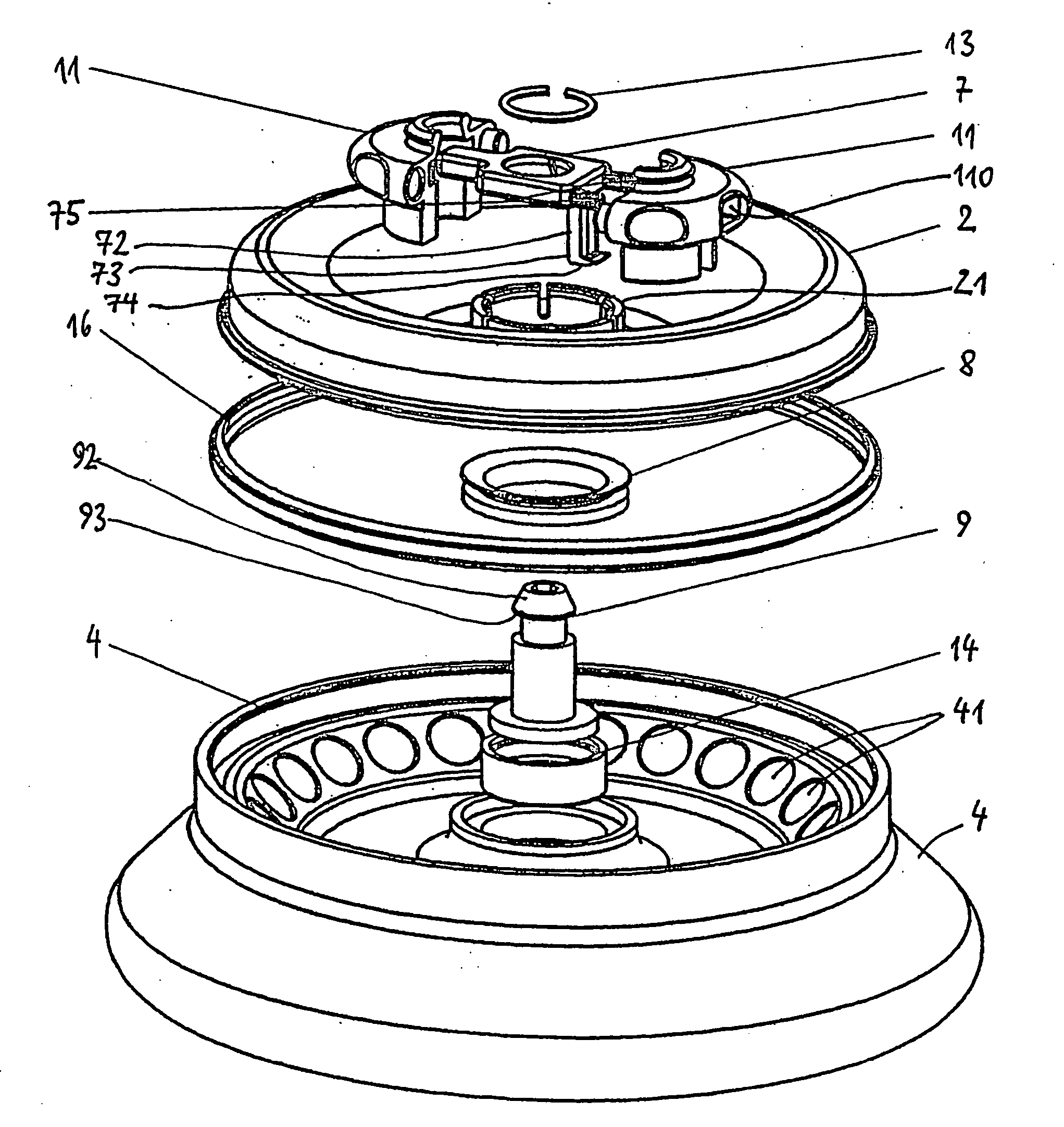
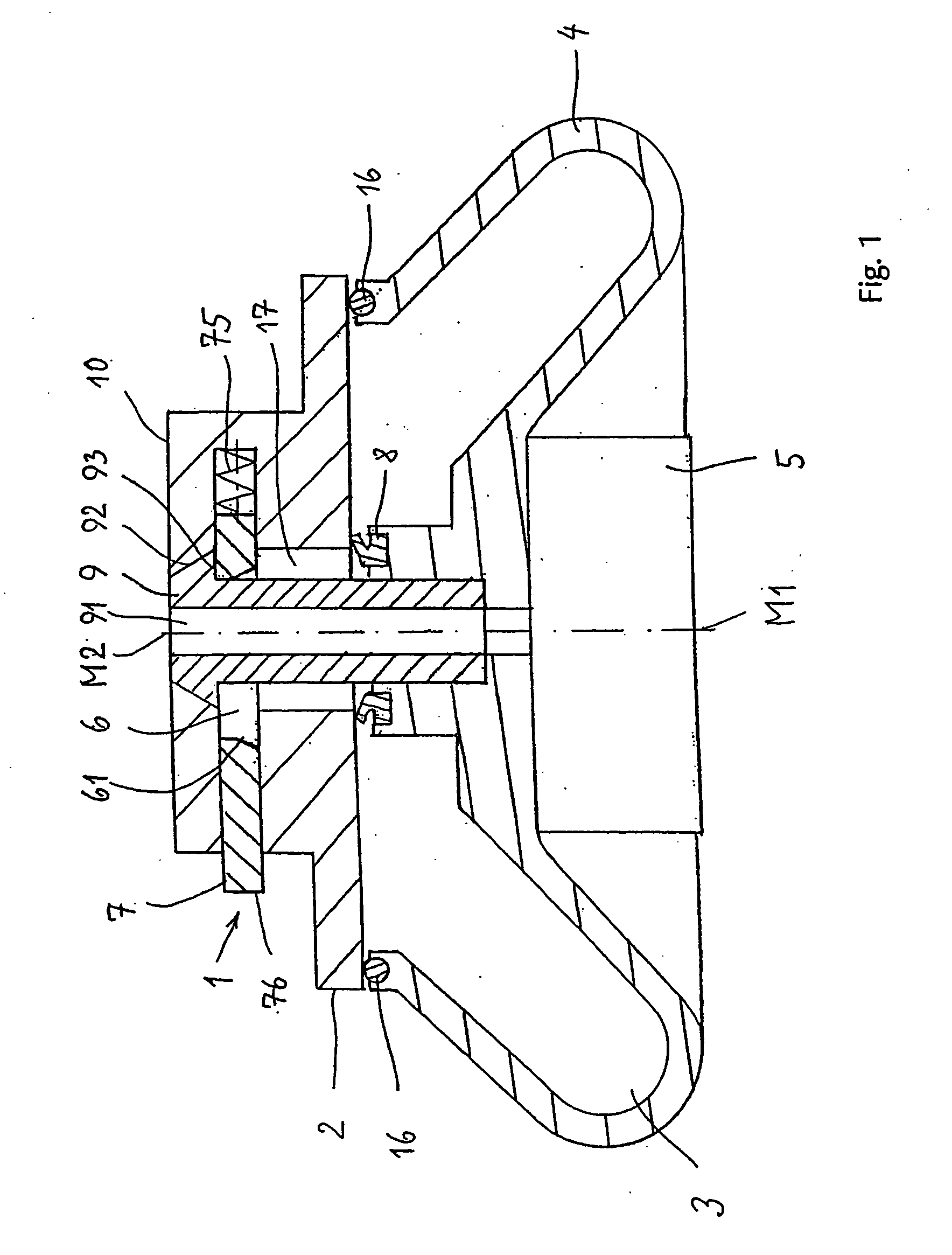
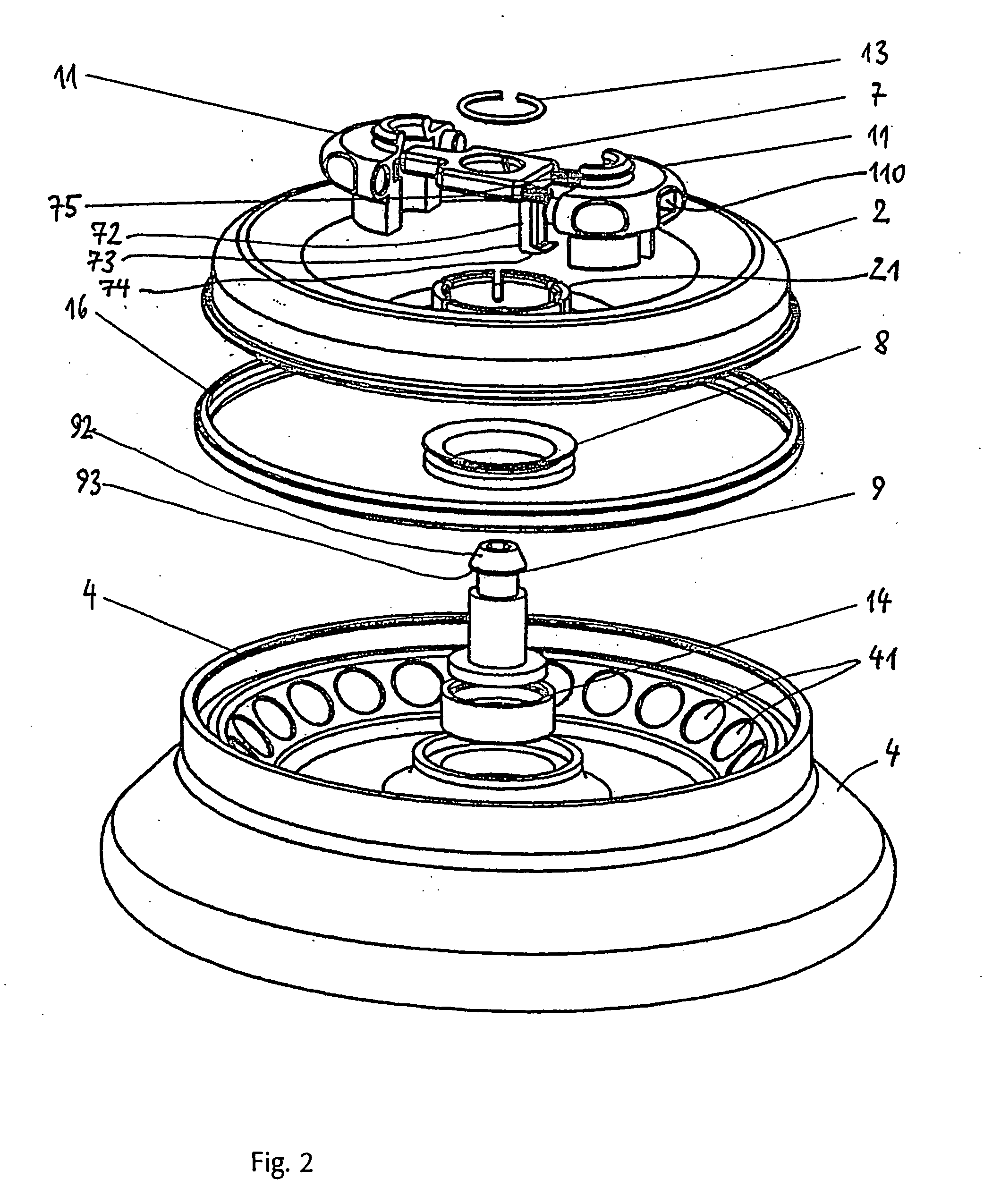
[0028]FIG. 1 shows a centrifuge rotor 4 having an associated closing device 2 in the form of a cover, using which a receiving chamber 3 in the form of an annular trough, which is formed by the centrifuge rotor 4 and the cover 2, may be closed. Containers having samples, which are subjected to a centrifugal force during operation of the centrifuge, may be received in the receiving chamber 3. The receiving chamber 3 is sealed by a first seal element 8 and a second seal element 16. The seal elements 8, 16 are preferably made of an elastic material.

[0029] The cover 2 is provided with a handle 10, which is implemented in one piece with the cover 2 in this embodiment. A fixing device 1 is provided in the handle 10, which has a catch element 7, which is received in the handle 10 so it is longitudinally displaceable. Using a compression spring 75, the catch element 7 is displaced into a locking position, a part 76 of the catch element 7 preferably partially projecting out of the handle 10 ...


PUM


Abstract

The present invention relates to a fixing device of a cover for a centrifuge rotor, a receiving chamber of the centrifuge rotor, which is driven using a drive unit, for receiving samples to be centrifuged being closable aerosol-fight using the cover. The fixing device is provided with an opening so that the drive unit is accessible through the fixing device and the cover without removing the cover. The present invention has the advantage that the rotor may be removed from the centrifuge and the rotor remains closed aerosol-fight at the same time. In addition, simple, one-handed operation is made possible.

Description

CROSS-REFERENCE TO RELATED APPLICATIONS [0001] This application claims priority to German patent application No. DE 102005014218.4 entitled, FIXING DEVICE FOR A CENTRIFUGE ROTOR COVER, filed Mar. 29, 2005, the disclosure of which is hereby incorporated by reference in its entirety. FIELD OF THE INVENTION [0002] The present invention relates to a fixing device of a cover for a centrifuge rotor, a receiving chamber of the centrifuge rotor, which is driven using a drive unit, for receiving samples to be centrifuged, being able to be closed aerosol-tight using the cover. BACKGROUND OF THE INVENTION [0003] For example, containers which are equipped with samples are received in a rotor of a centrifuge. At high speeds of the centrifuge, such strong forces act on the samples that separation into different components of the samples may be achieved. In order to increase safety during operation of a centrifuge, the opening of the rotor is closed using a closing device implemented as a cover be...

Claims


Application Information

Patent Timeline
IPC IPC(8): B04B7/02
CPCB04B2007/025B04B5/0414B04B5/04B04B5/0407B04B7/02B04B7/06
Inventor HENNE, SEBASTIAN
Owner THERMO ELECTRONICS LED GMBH
Learn More