Optimized cluster tool transfer process and collision avoidance design

a technology of collision avoidance design and transfer process, applied in the direction of program control, printers, total factory control, etc., can solve the problems of large sequence, short chamber processing time, and large processing steps, and achieve the effect of improving the trajectory path

Inactive Publication Date: 2006-10-26
SOKUDO CO LTD
View PDF99 Cites 58 Cited by
  • Summary
  • Abstract
  • Description
  • Claims
  • Application Information

AI Technical Summary

Benefits of technology

[0011] Embodiments of the invention generally provide apparatus and method for improving trajectory paths and collision avoidance.

Problems solved by technology

In an effort to reduce CoO, electronic device manufacturers often spend a large amount of time trying to optimize the process sequence and chamber processing time to achieve the greatest substrate throughput possible given the cluster tool architecture limitations and the chamber processing times. In some cluster tools, for example track lithography type cluster tools, the chamber processing times tend to be rather short, (e.g., about a minute to complete the process) and the number of processing steps required to complete a typical process sequence is large, a significant portion of the time it takes to complete the processing sequence is taken up in transferring the substrates between the various processing chambers.
The longest process recipe step will generally limit the throughput of the processing sequence.
A track lithography process sequences is generally robot limited due to the short processing times and large number of processing steps.
However, the path using the shortest time may take too much space causing collision with the cluster tool, other robots or even the robot itself.
The sensing and determining steps take extra time and slow down the robot.
Sometimes, the robot has to stand still and wait for its turn to use a space, which further slows down the system.

Method used


Image

  • Optimized cluster tool transfer process and collision avoidance design
  • Optimized cluster tool transfer process and collision avoidance design
  • Optimized cluster tool transfer process and collision avoidance design

Examples


Embodiment Construction

[0026] Embodiments of the invention generally provide an apparatus and method for processing substrates using a multi-chamber processing system, e.g., a cluster tool which has robots with optimized trajectory paths and collision avoidance.

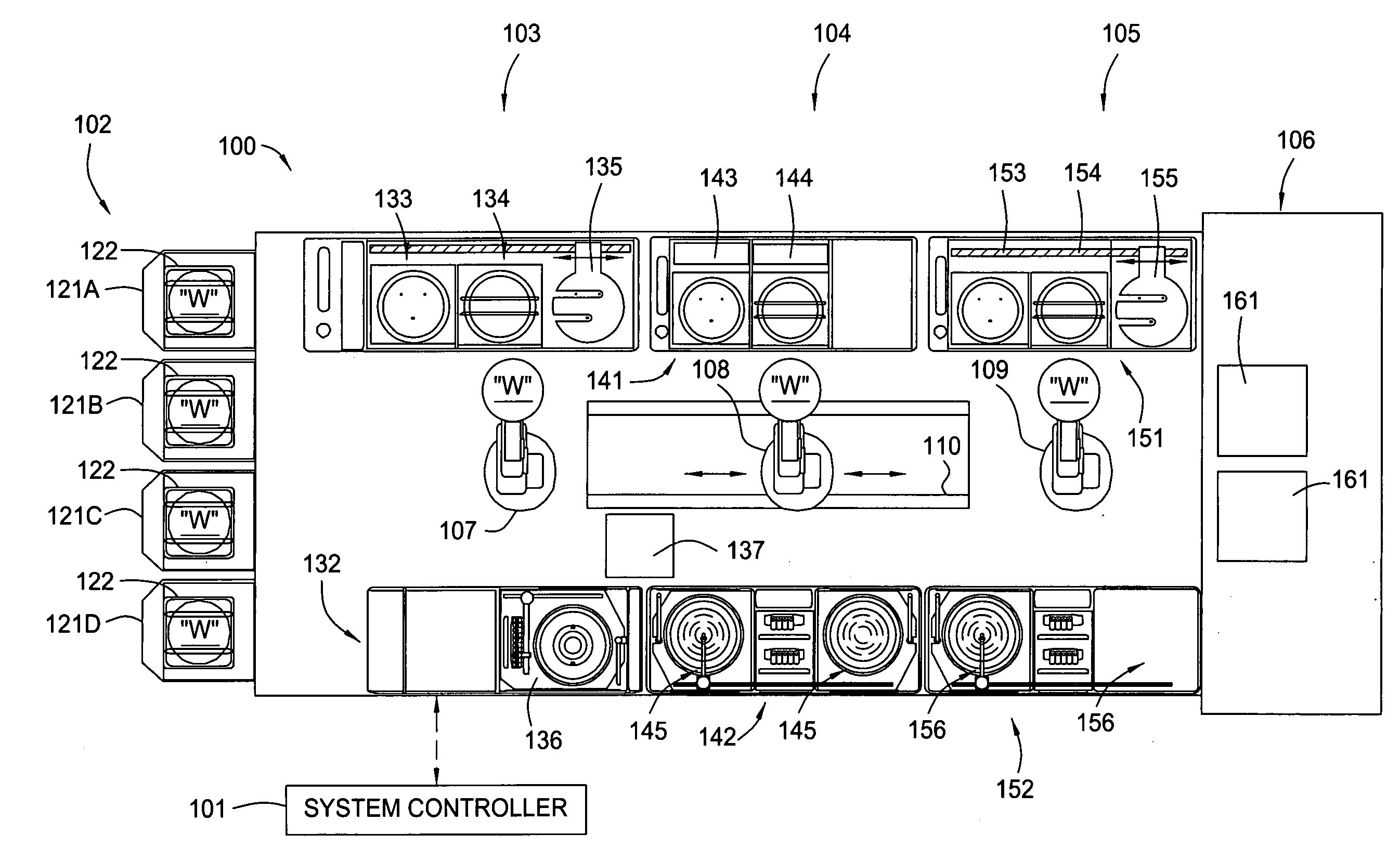
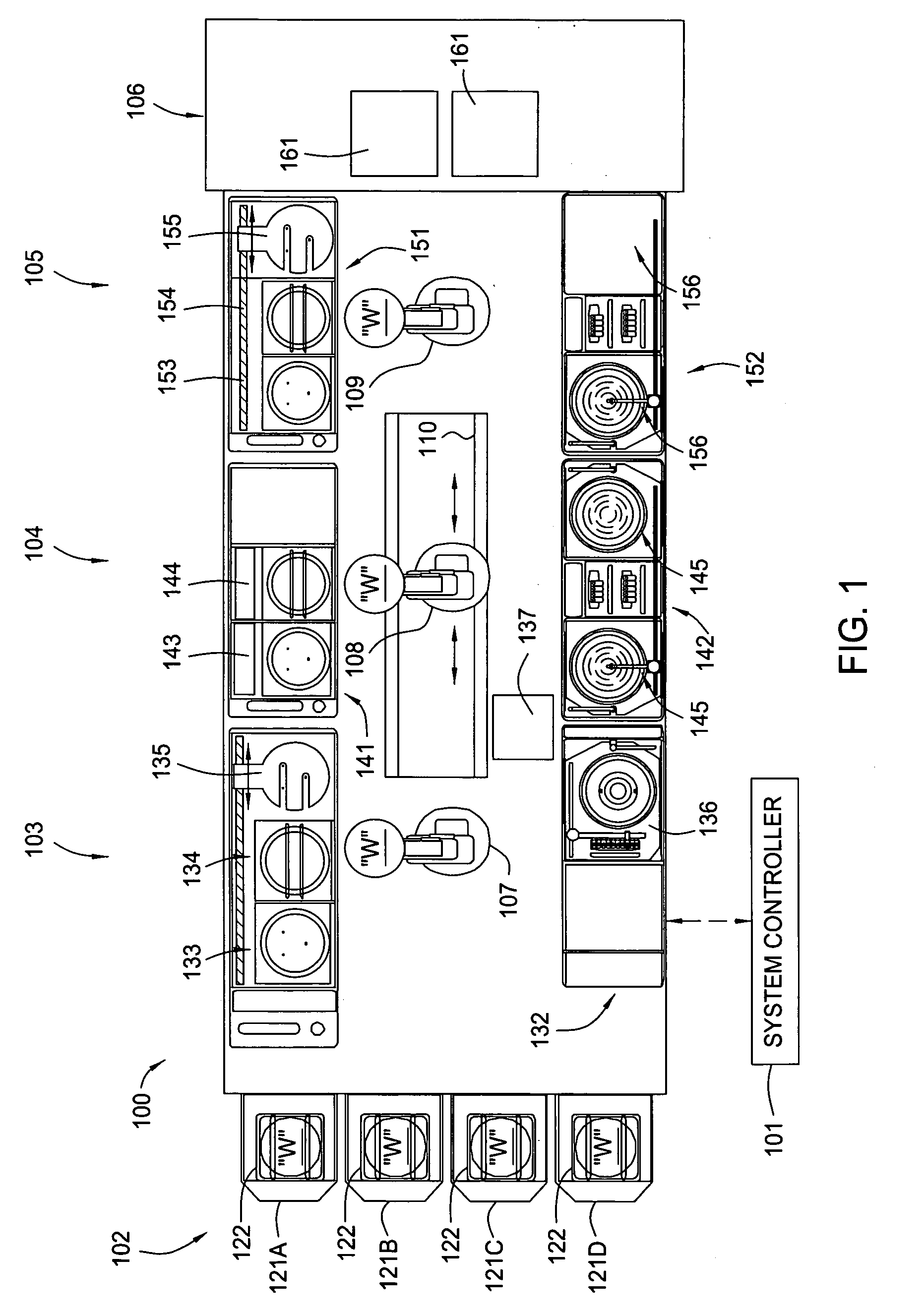
[0027]FIG. 1 illustrates a schematic top view of a cluster tool 100 in accordance with one embodiment of the present invention. The cluster tool 100 generally comprises a system controller 101, a factory interface module 102 configured to receive and store substrates from a factory environment, a front module 103 disposed next to the factory interface module 102, a central module 104, a rear module 105 and a stepper module 106. The front, central and rear modules 103, 104 and 105 each comprises two racks of stacked processing chambers disposed on opposite sides.

[0028] Generally, a processing rack may contain one or more processing chambers, such as one or more coater chambers, one or more developer chamber, one or more bake / chill chambers. In a p...


PUM


Abstract

The present invention relates to apparatus and method of collision avoidance in a cluster tool having a plurality of processing stations and at least two robots. In one embodiment of the invention, the system is configured such that each of the processing stations is accessible by only one of the at least two robots. For each of the at least two robots, a set of trajectories is determined so that each robot is capable of transferring substrates among the corresponding processing stations, wherein the envelope formed by the set of trajectories of each robot does not overlap.

Description

CROSS-REFERENCE TO RELATED APPLICATIONS [0001] This application is a continuation in part of U.S. patent application Ser. No. 11 / 112,281, filed on Apr. 22, 2004, entitled “Cluster Tool Architecture for Processing a Substrate”, which is herein incorporated by reference.BACKGROUND OF THE INVENTION [0002] 1. Field of the Invention [0003] Embodiments of the present invention generally relate to apparatus and method for transferring semiconductor substrates in an integrated processing system. [0004] 2. Description of the Related Art [0005] In modern semiconductor processing, multilayered features are fabricated on semiconductor substrates in a cleanroom environment using specific processing recipes having many processing steps. A cluster tool, which integrates a number of process chambers to perform a sequential processing steps without removing substrates from a highly controlled processing environment, is generally used in processing semiconductor substrates. The process chambers may i...

Claims


Application Information

Patent Timeline
Patent Type & Authority Applications(United States)
IPC IPC(8): G05B19/04
CPCG03B27/32H01L22/26G03F7/40G05B19/41825G05B2219/40476G05B2219/45031G05B2219/49137H01L21/67109H01L21/6715H01L21/67161H01L21/67173H01L21/67178H01L21/67184H01L21/6719H01L21/67196H01L21/67225H01L21/67742H01L21/67745H01L21/67748H01L21/67754H01L21/6831H01L21/6838H01L21/68707G03D13/006Y02P90/02
Inventor BABU, VENKATESHKAPLAN, RUSSELLISHIKAWA, TETSUYA
Owner SOKUDO CO LTD
Why Eureka
Try Eureka