Crop take-up assembly and harvesting machine

a technology of take-up rotor and take-up rotor, which is applied in the field of take-up assembly, can solve the problems of difficult movement of obstructions in the area of take-up rotor of such assemblies, interlocking of the tines of the take-up rotor, etc., and achieves the effect of reducing the possibility of obstruction and allowing entry of the tines into the guide tracks

Inactive Publication Date: 2006-11-02
DEERE & CO
View PDF6 Cites 10 Cited by
  • Summary
  • Abstract
  • Description
  • Claims
  • Application Information

AI Technical Summary

Benefits of technology

[0006] The invention proposes a crop take-up assembly with a take-up rotor that is provided with tines and a first guide assembly enclosing the tines in an upper, forward and lower region. The first guide assembly defines guide tracks, wherein the tines are guided along a curved path during normal operation. According to the present invention, a second guide assembly is provided in a region to the rear of the direction of conveying. The second guide assembly guides the tines in the direction of the guide tracks during a reversal of the take-up rotor. In this way the take-up rotor can also be reversed or moved in a direction opposite to the normal conveying direction, for removal of an obstruction for example, or to eject metallic objects or stones, without causing the tines to interlock as a result of misalignment with the first guide tracks. The first and second guide assemblies are preferably configured as multi-piece components, however, a one-piece configuration is also conceivable.
[0009] In yet another aspect, the entry of the tines into the guide tracks is improved due to the guide tracks being narrowed in the direction of an upper open end region of the guide tracks of the first guide assembly. In this way the tines are guided into the guide tracks of the first guide assembly. The entry into the guide track of the second guide assembly from the first guide assembly can be performed in a wide region, where, in turn, an interlocking of the tines or obstruction can be prevented.

Problems solved by technology

Otherwise, this could lead to an interlocking of the tines of the take-up rotor.
Not having the ability to reverse this makes it difficult to move obstructions in the area of the take-up rotor of such assemblies.

Method used


Image

  • Crop take-up assembly and harvesting machine
  • Crop take-up assembly and harvesting machine
  • Crop take-up assembly and harvesting machine

Examples


Embodiment Construction

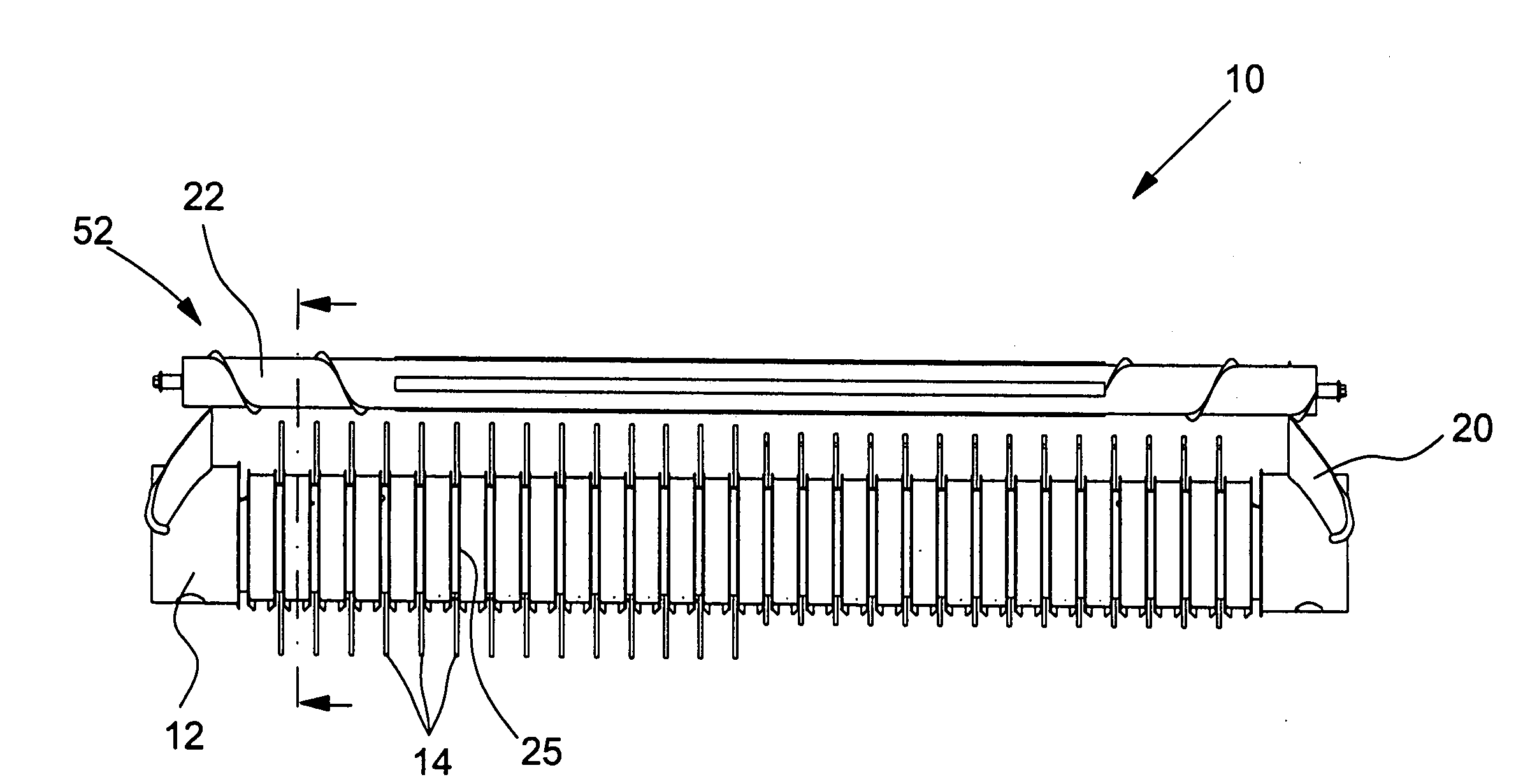
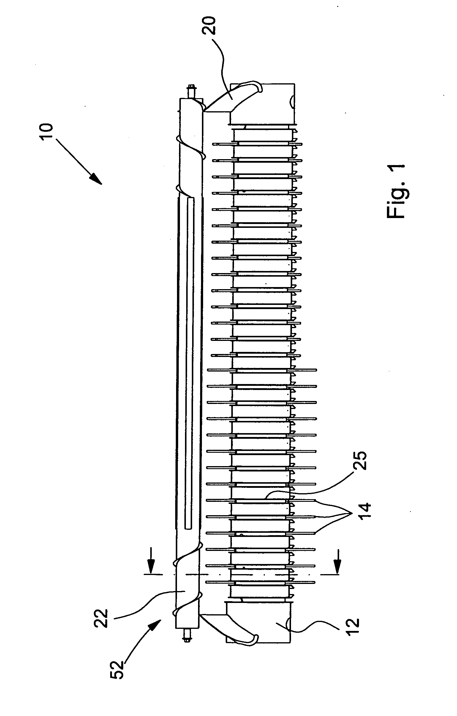
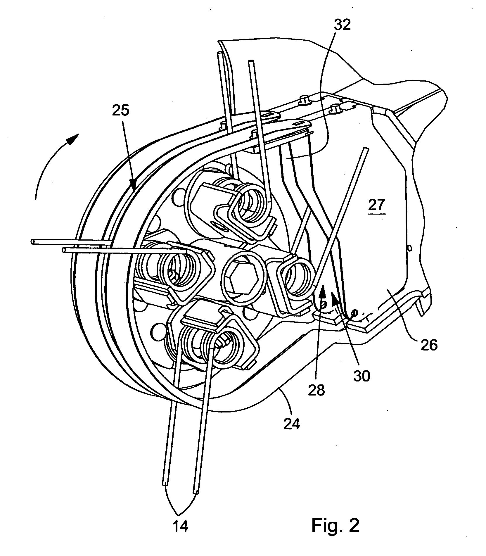
[0013] Referring to FIG. 1, a crop take-up assembly for an agricultural harvesting machine, such as a forage harvester, a combine or a baler, in accordance with the present invention is shown therein and generally designated at 10. The crop take-up assembly 10 includes a take-up rotor 12 with a plurality of tines 14 attached to the circumference thereof. The take-up rotor 12 and the tines 14 convey the crop in overshot manner. That is, and as shown in FIG. 2, the take-up rotor 12 rotates counter-clockwise. The tines 14 are rod-like members flexibly suspended from torsion or spiral springs 16. The take-up rotor 12 is rotatably supported by bearings within a take-up frame. Preferably the height of the take-up rotor 12 above the ground can be adjusted.

[0014] Sheet metal guide vanes 20 are provided at the side, toward both ends, of the take-up rotor 12 of the crop take-up assembly 10. The guide vanes 20 are intended to prevent the crop being taken up from falling sideways off the crop ...


PUM


Abstract

A crop take-up assembly having a rotatable take-up rotor with tines mounted thereon. A first guide assembly encloses the tines in an upper, forward and lower region, and defines a first set of guide tracks in which the tines are guided along a curved path. A second guide assembly encloses the tines in a rear region. The second guide assembly guides the tines into the first set of guide tracks during a reversal of rotation of the take-up rotor.

Description

[0001] 1. Field of the Invention [0002] The invention relates to a crop take-up assembly having a take-up rotor equipped with tines. [0003] 2. Background of the Invention [0004] Known crop take-up assemblies are provided with a take-up rotor having an overrunning clutch so that it does not reverse in the event of a reversal of the crop take-up assembly. Otherwise, this could lead to an interlocking of the tines of the take-up rotor. Not having the ability to reverse this makes it difficult to move obstructions in the area of the take-up rotor of such assemblies. [0005] In view of the above limitations and drawbacks, there is a need for a crop take-up assembly which will allow easier removal of obstructions in the area of the take-up rotor. SUMMARY [0006] The invention proposes a crop take-up assembly with a take-up rotor that is provided with tines and a first guide assembly enclosing the tines in an upper, forward and lower region. The first guide assembly defines guide tracks, whe...

Claims


Application Information

Patent Timeline
Patent Type & Authority Applications(United States)
IPC IPC(8): A01D57/00
CPCA01D89/002
Inventor POURCHET, JEREMYJOSSET, ETIENNE
Owner DEERE & CO
Why Eureka
Try Eureka