Surface roughness/contour profile measuring instrument

a technology of contour profile and measuring instrument, which is applied in the direction of instruments, mechanical roughness/irregularity measurements, measurement devices, etc., can solve the problems of preventing the operator from doing other work in the meantime, affecting the measurement position, and affecting the measurement accuracy

Inactive Publication Date: 2006-11-02
TOKYO SEIMITSU
View PDF2 Cites 6 Cited by
  • Summary
  • Abstract
  • Description
  • Claims
  • Application Information

AI Technical Summary

Benefits of technology

[0016] Further, the technique of the movement path automatic setting of a contact probe in a coordinate measuring instrument is premised on the use of the function of the coordinate measuring instrument for measuring the coordinates of a complex three-dimensional form, therefore, an operator is able to set a complex path easily. In contrast to this, a surface roughness / contour profile measuring instrument assumes that the above-mentioned operation is performed by an operator and, therefore, it does not have the function of performing a complex movement in the three-dimensional space or the function of easily setting such a path. Because of this, a technique capable of easily performing the movement path automatic setting of a pickup in a current surface roughness / contour profile measuring instrument is demanded.
[0029] A generated path consists of only the movement of the pickup in the detection direction (Z direction) and the movement in the direction perpendicular to that (movement in the X-Y plane) outside the safe range, and a path can be generated easily. Further, outside the safe range, the pickup does not move in the direction perpendicular to the detection direction of the pickup in a state of being lower in height than the reference position, therefore, collision of the contact probe with a work can be avoided.
[0030] According to the surface roughness / contour profile measuring instrument of the present invention, by only doing a predetermined simple setting, it is possible to automatically perform the operation to move the pickup to the measurement directed position.

Problems solved by technology

Therefore, there is a problem in that it is necessary for the operator to always stay by the surface roughness / contour profile measuring instrument during the period of measurement to monitor the measurement, preventing the operator from doing other work in the meantime.
If the distance is increased, as described above, it is necessary to move the contact probe 7 from the position PR to the contact position PM in FIG. 2 at low speed and there is a problem in that the operation time is lengthened.
In the case of a non-contact type pickup, it is difficult to judge the measurement position and the above-mentioned problem becomes more remarkable in the case of a non-contact type pickup.
However, the contact probe of the coordinate measuring instrument has a larger detection possible range than that of the contact probe of a surface roughness / contour profile measuring instrument and the current state is that the automatic movement contact technique of the contact probe in the coordinate measuring instrument is difficult to apply to a surface roughness / contour profile measuring instrument.
Because of this, a surface roughness / contour profile measuring instrument that automatically moves and causes a contact probe to come into contact with a work (movement of a pickup to a measurement directed position) has not been realized so far.

Method used


Image

  • Surface roughness/contour profile measuring instrument
  • Surface roughness/contour profile measuring instrument
  • Surface roughness/contour profile measuring instrument

Examples


Embodiment Construction

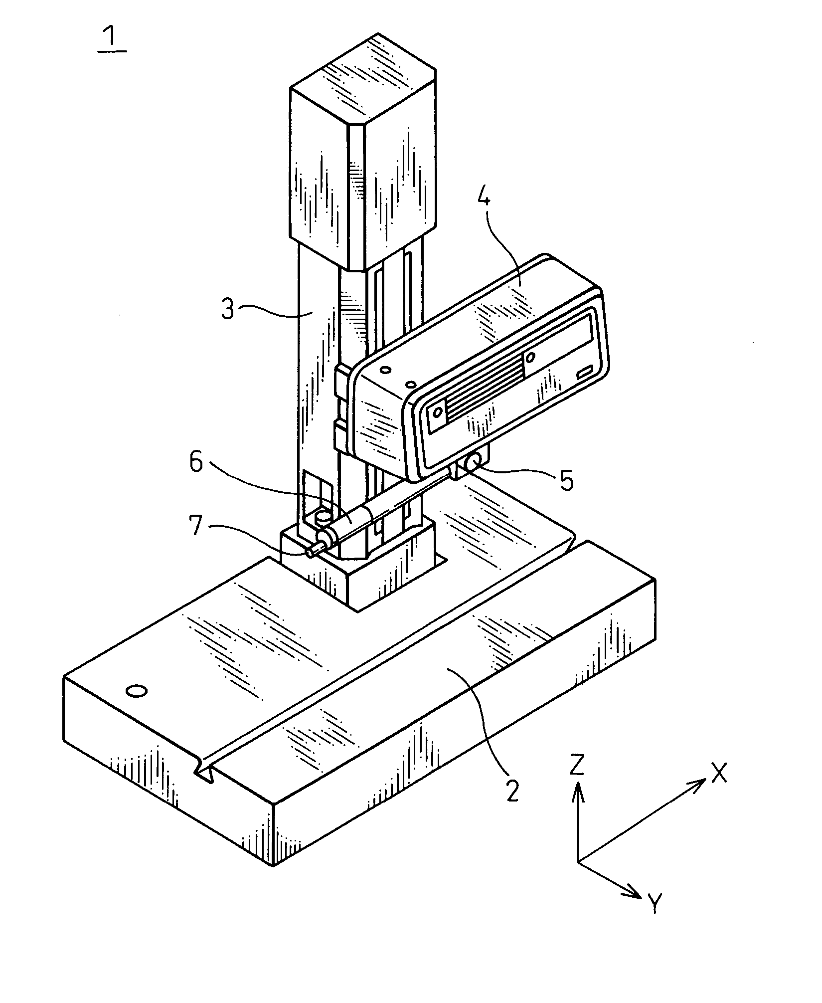
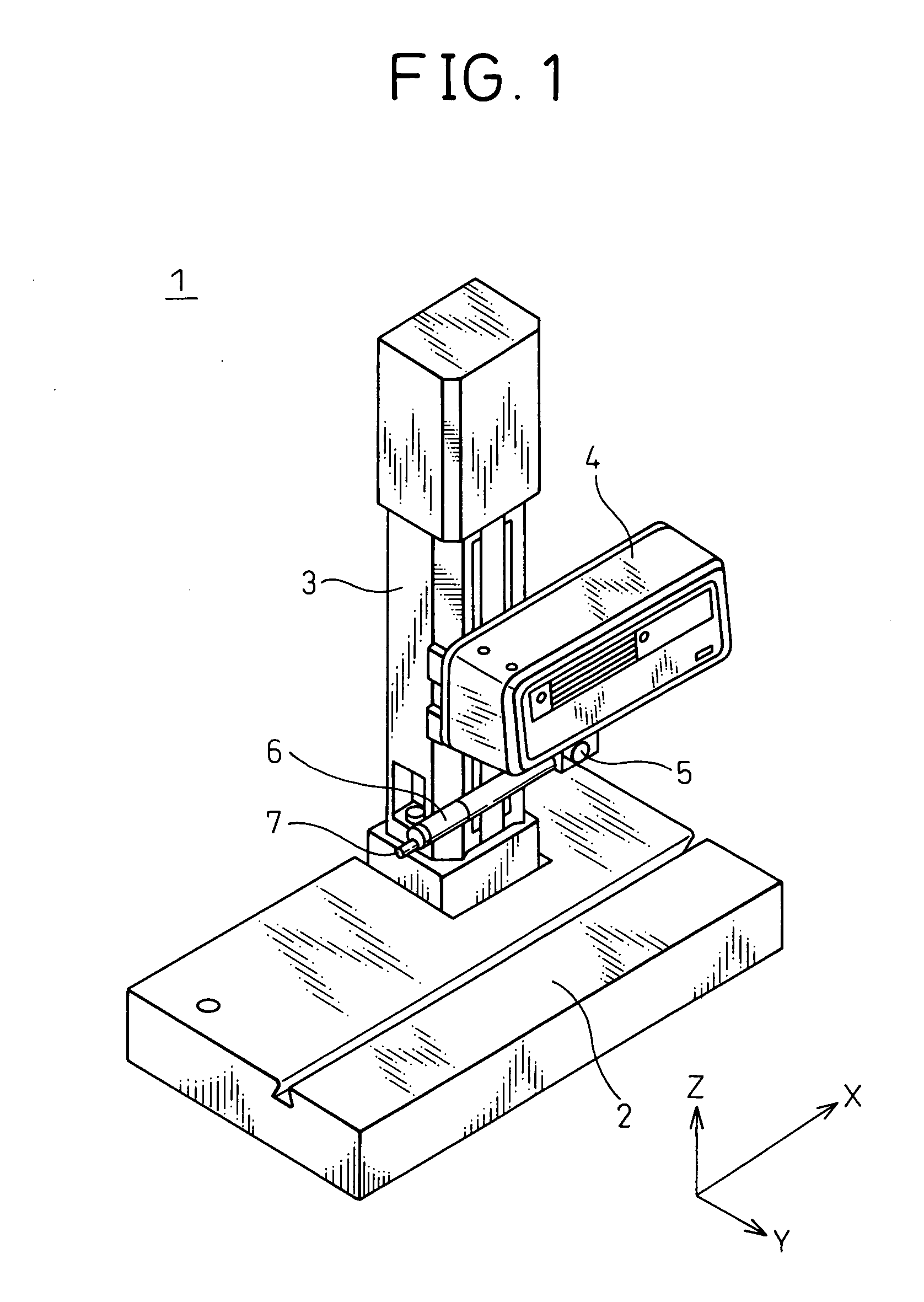
[0039] A surface roughness / contour profile measuring instrument in an embodiment of the present invention is explained below. The surface roughness / contour profile measuring instrument in the embodiment is capable of moving a pickup three-dimensionally as shown in FIG. 1, however, the present invention is not limited to this and can be applied to an instrument capable of moving a pickup two-dimensionally. Further, it is only necessary to be capable of relatively moving a pickup two- or three-dimensionally with respect to a work, and it is also possible to realize part of movement by moving the work and to realize movement by rotational movement not only by translational movement.

[0040] Further, the present invention can also be applied to a surface roughness / contour profile measuring instrument having a pickup of a type that detects the surface position in a non-contact manner such as an optical method etc.

[0041]FIG. 3 is a diagram showing a configuration of a surface roughness / co...


PUM


Abstract

A surface roughness / contour profile measuring instrument capable of automatic movement of a pickup to a measurement position has been disclosed. The surface roughness / contour profile measuring instrument comprises a pickup and a pickup moving mechanism and measures the surface roughness or the contour profile of the surface of a work, and further comprises a movement information generation section for generating movement information necessary to move the pickup from the current position to the measurement position for detecting the height of a surface position on the work surface and a movement control section for relatively moving the pickup with respect to the work based on the movement information generated by the movement information generation section.

Description

BACKGROUND OF THE INVENTION [0001] The present invention relates to a surface roughness / contour profile measuring instrument and, more particularly, to a surface roughness / contour profile measuring instrument having an improved ability to cause a contact probe to come into contact with a measurement part of a work. [0002] The surface roughness / contour profile measuring instrument measures the surface roughness or the contour profile of a work by moving a pickup having a contact probe along the surface of a work, converting the amount of displacement of the pickup into an electric signal, and reading the displacement using a calculating machine such as a computer. Such a configuration is disclosed in, for example, Japanese Unexamined Patent Publication (Kokai) No. 2002-107144. FIG. 1 shows a basic configuration of a conventional surface roughness / contour profile measuring instrument. [0003] A surface roughness / contour profile measuring instrument 1 has a pickup 6 for measuring the su...

Claims


Application Information

Patent Timeline
Patent Type & Authority Applications(United States)
IPC IPC(8): G01B5/28
CPCG01B21/30
Inventor AOKI, YUYA
Owner TOKYO SEIMITSU
Why Eureka
Try Eureka