Control system for electrochromic devices

a control system and electrochromic technology, applied in the field of electrochromic devices, can solve the problems of voltages exceeding 2.5v that damage the electrochromic device, and achieve the effect of effective control of the electrochromic devi

Active Publication Date: 2006-11-02
SAGE ELECTROCHROMICS
View PDF9 Cites 124 Cited by
  • Summary
  • Abstract
  • Description
  • Claims
  • Application Information

AI Technical Summary

Problems solved by technology

At relatively high temperatures (e.g. 70 C), an electrochromic device may be damaged by voltages exceeding 2.5V.

Method used


Image

  • Control system for electrochromic devices
  • Control system for electrochromic devices
  • Control system for electrochromic devices

Examples


Embodiment Construction

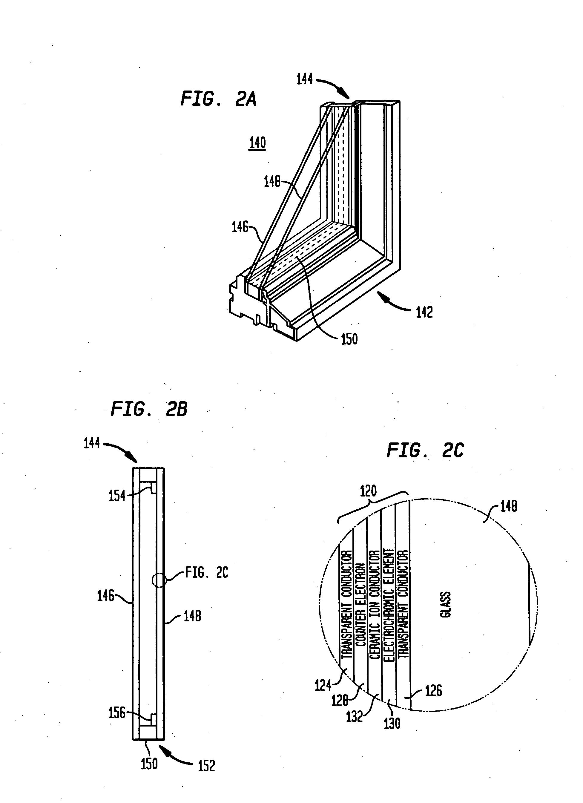
[0056]FIGS. 2A and 2B show an electrochromic window 140, in accordance with certain preferred embodiments of the present invention. The electrochromic window 140 includes a window frame 142 securing an insulated glass unit 144 comprising a first glass pane 146 and a second glass pane 148. The insulated glass unit 144 also includes a spacer 150 and a seal 152 for forming an air-tight compartment between the first and second glass panes 146, 148. The interior space between the first and second glass panes 146, 148 is filled with an inert gas, such as air or argon.

[0057] Referring to FIGS. 2B and 2C, an electrochromic device 120 is secured over the second glass pane 148 of the insulated glass unit 144. The electrochromic device 120 includes a first transparent conductor 124 and the second transparent conductor 126 in contact with second glass pane 148. The electrochromic device 120 also includes a counter electrode 128 in contact with the first transparent conductor 124, an electrochr...


PUM

PropertyMeasurementUnit
voltagesaaaaaaaaaa
voltageaaaaaaaaaa
voltageaaaaaaaaaa

Abstract

A method of determining the transmission state of an electrochromic device includes applying a voltage across the electrochromic device, using the applied voltage and current for calculating leakage current of the electrochromic device and determining ionic current as the difference between the applied current and the leakage current. The method includes using the ionic current for determining the transmission state of the electrochromic device.

Description

CROSS-REFERENCE TO RELATED APPLICATIONS [0001] The present application is a divisional of commonly assigned U.S. patent application Ser. No. 10 / 897,851, filed Jul. 23, 2004, the disclosure of which is hereby incorporated by reference herein.BACKGROUND OF THE INVENTION [0002] The present invention generally relates to electrochromic devices and more particularly relates to control systems for electrochromic devices. [0003] Electrochromic devices include electrochromic materials that change their optical properties in response to the application of an electric current or an electric potential. Electrochromic devices generally include a series of thin films that are deposited directly onto the surface of a transparent substrate, such as a conventional window made of glass or plastic. Electrochromic devices are typically incorporated into architectural and transportation window applications, display windows and cabinets, or any application requiring a changeable tinted glass. By selecti...

Claims


Application Information

Patent Timeline
Patent Type & Authority Applications(United States)
IPC IPC(8): G02F1/15G02F1/163G08B13/04
CPCY10S359/90G02F1/163
Inventor GREER, BRYAN D.
Owner SAGE ELECTROCHROMICS
Why Eureka
Try Eureka