
Microscope

Active Publication Date: 2006-11-02
EVIDENT CORP
View PDF6 Cites 3 Cited by
  • Summary
  • Abstract
  • Description
  • Claims
  • Application Information

AI Technical Summary

Benefits of technology

[0014] The present invention has been conceived in light of the circumstances described above, and an object thereof is to provide a microscope in which the exposure time for obtaining a bright image in an image-acquisition optical system can be reduced and in which image shifting can be prevented in an observation optical system, thus enabling stable observation.

Problems solved by technology

In optical systems for image acquisition, the conventional concepts of effective magnification and empty magnification are not necessarily applicable.
On the other hand, if the range of overall effective magnifications is exceeded and a low magnification is set, not only is the resolution of the eye lower than the resolution of the optical system, thus not making full use of the resolving power of the microscope, but if the eye shifts when observing a comparatively deep specimen with the microscope, there is also a problem in that the image wobbles and becomes difficult to see.
Although there are differences in the way observers perceive things, this nevertheless causes unstable vision and may even result in nausea when observing for a long period of time.

Method used


Image

  • Microscope
  • Microscope
  • Microscope

Examples


Embodiment Construction

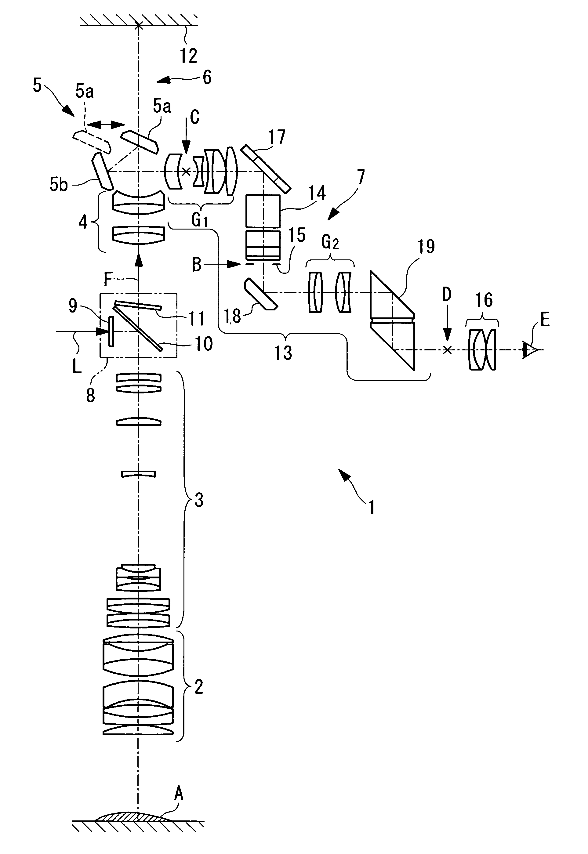
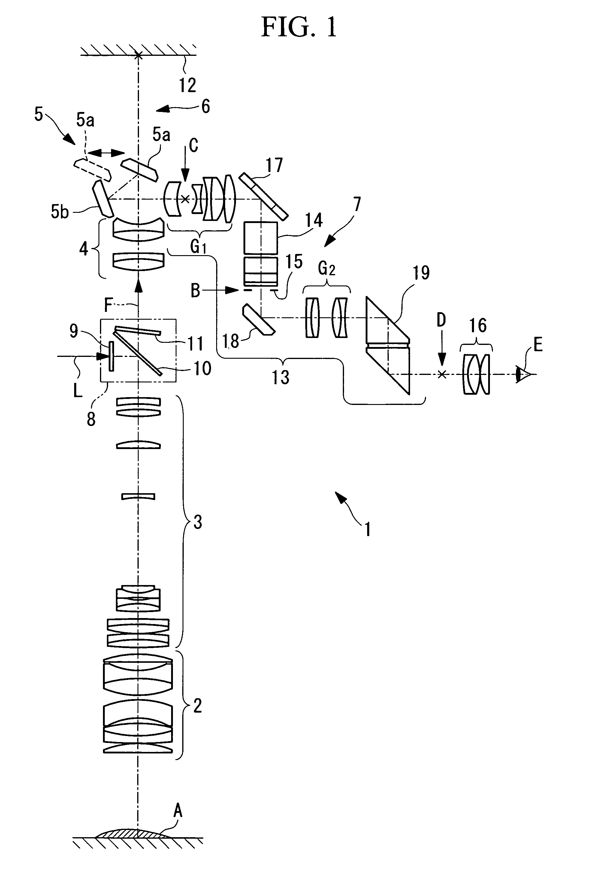
[0080] A microscope 1 according to an embodiment of the present invention will be described below with reference to FIGS. 1 to 8.

[0081] As shown in FIG. 1, the microscope 1 according to this embodiment includes, in order from a specimen A side, an objective optical system 2 for collecting light from the specimen A; a variable-magnification optical system 3 which can vary the magnification of an image; an image-forming lens 4 for forming an image of the light that has passed through the variable-magnification optical system 3; a first optical-path-splitting member 5, disposed after the image-forming lens 4, for splitting the optical path; and an image-acquisition optical path 6 and an observation optical path 7, which are split-off by the first optical-path-splitting member 5. A filter set 8 for introducing illumination light L is disposed between the variable-magnification optical system 3 and the image-forming lens 4. An optical system for the illumination which is incident on the...


PUM


Abstract

The exposure time for obtaining a bright image in an image-acquisition optical system can be reduced, and shifting of an image visually observed in an observation-optical system is prevented, thus enabling stable observation. There is provided a microscope including an image-acquisition optical path for recording an image focused by an objective lens and an observation optical path for visually observing an image split-off from the image-acquisition optical path; and including an aperture stop, in the observation optical path, for stopping down the numerical aperture thereof to smaller than the numerical aperture of the image-acquisition optical path.

Description

BACKGROUND OF THE INVENTION [0001] 1. Field of the Invention [0002] The present invention relates to optical microscopes, and more particularly, to a microscope including an observation optical path for visual observation of an image and an image-acquisition optical path for recording an image. [0003] This application is based on Japanese Patent Application No. 2005-126593, the content of which is incorporated herein by reference. [0004] 2. Description of Related Art [0005] Conventionally, because the main application of microscopes has been observation with the eye, their optical specifications have been set within ranges suitable for visual observation (for example, see Principles of Biological Microscopes by Akihiro YOUKA, published by Baifukan, 20 Jun. 1973, Chapter 3, Objective Lenses). [0006] According to Principles of Biological Microscopes by Akihiro YOUKA, published by Baifukan, 20 Jun. 1973, Chapter 3, Objective Lenses, the following expression gives the range of overall e...

Claims


Application Information

Patent Timeline
IPC IPC(8): G02B21/00
CPCG02B21/361
Inventor HAYASHI, KAZUHIROSHIMIZU, KEIJI
Owner EVIDENT CORP
Learn More