
Process cartridge and image forming apparatus

a technology of electrophotographic image and process cartridge, which is applied in the direction of electrographic process apparatus, instruments, optics, etc., to achieve excellent effects

Inactive Publication Date: 2006-11-02
CANON KK
View PDF17 Cites 109 Cited by
  • Summary
  • Abstract
  • Description
  • Claims
  • Application Information

AI Technical Summary

Benefits of technology

[0010] Each of the structural arrangements disclosed in the abovementioned documents displays excellent effects. However, in the cases of these structural arrangements, it has not been taken into consideration that an image forming apparatus is transported with a cartridge (cartridges) mounted in the main assembly of the image forming apparatus.
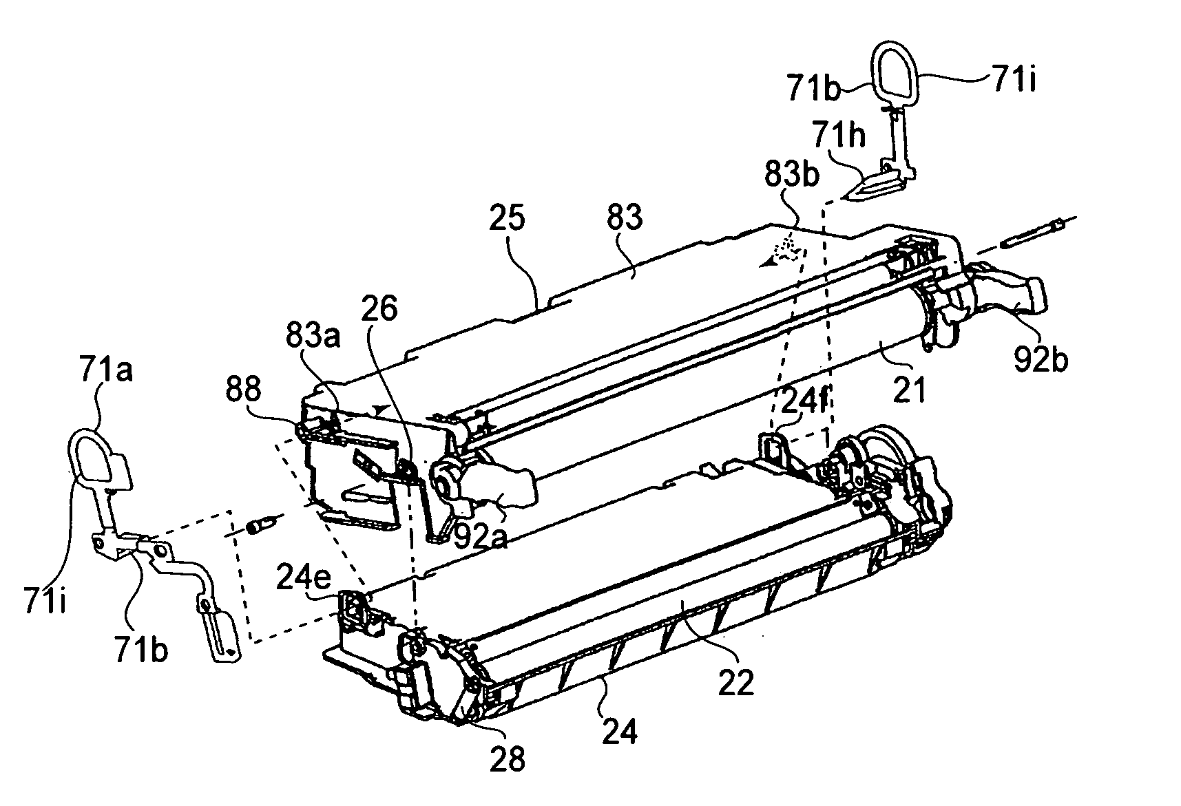
[0012] Another object of the present invention is to provide a process cartridge which allows the separating members remaining attached thereto to be detected before an image forming operation is started, and an electrophotographic image forming apparatus in which such a process cartridge is removably mountable. Here, the separating member means a member which is attached to a process cartridge to separate, and keep separated, the photosensitive member and development roller from each other.

Problems solved by technology

However, in the cases of these structural arrangements, it has not been taken into consideration that an image forming apparatus is transported with a cartridge (cartridges) mounted in the main assembly of the image forming apparatus.

Method used


Image

  • Process cartridge and image forming apparatus
  • Process cartridge and image forming apparatus
  • Process cartridge and image forming apparatus

Examples


embodiment 1

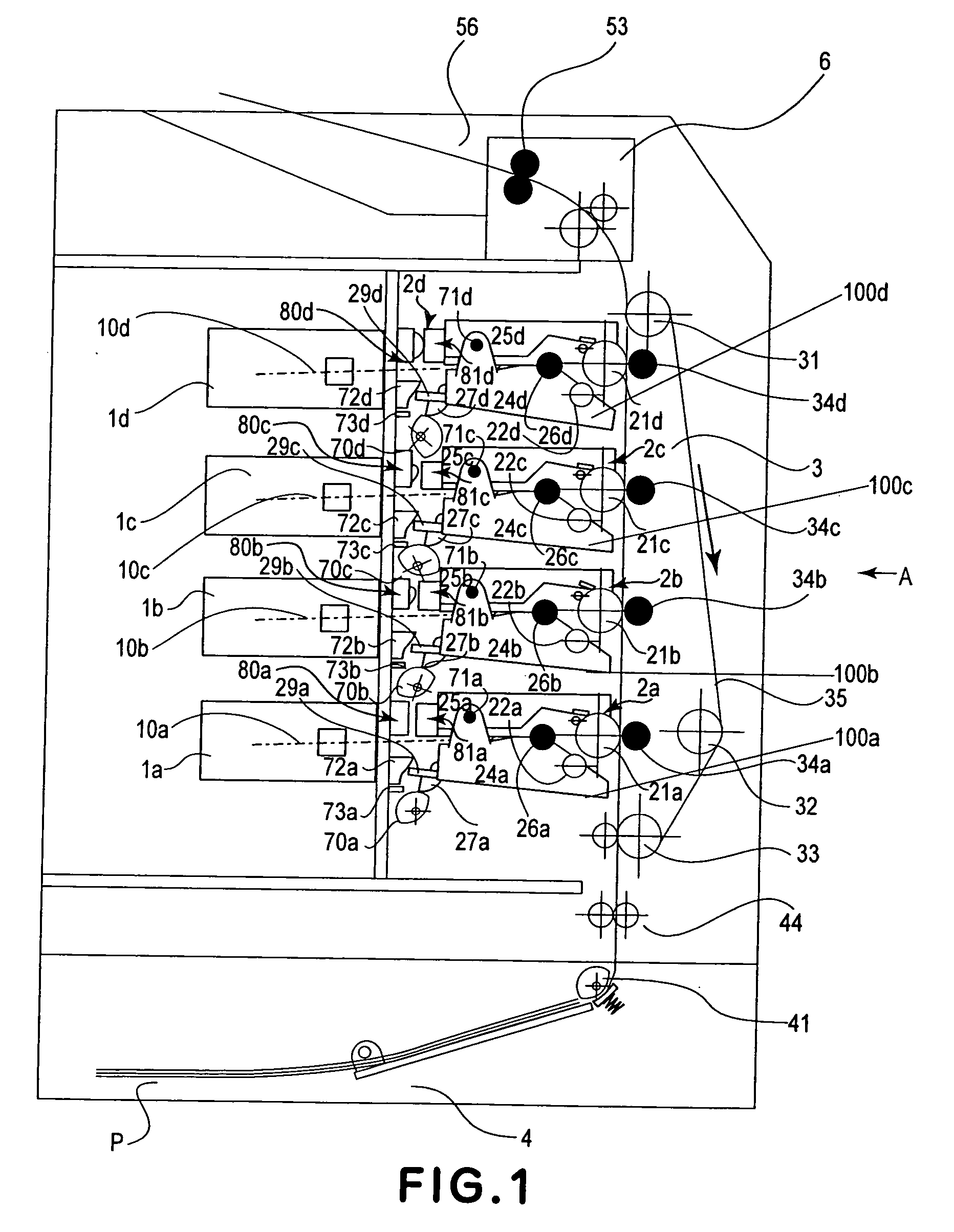
[0050] Next, the electrophotographic image forming apparatus in the first embodiment of the present invention will be described with reference to the appended drawings. FIG. 1 is a sectional view of a color laser printer, as an example of an electrophotographic color image forming apparatus, in the first embodiment of the present invention, showing the general structure thereof.

[General Structure of Image Forming Apparatus]

[0051] First, referring to FIG. 1, the general structure of the color image forming apparatus will be described. The image forming apparatus 100 has: cartridge bays 100 (100a, 100b, 100c, and 100d), in which the cartridges are removably mountable; detection levers 72; and sensors 73. Each sensor 73 as a detecting means detects whether or not the separating members 71 are remaining on the cartridge 2, when the cartridge 2 is mounted into the apparatus main assembly 100. The structures of the abovementioned components will be described later in detail.

[0052] The ...

embodiment 2

[0122] Next, the image forming apparatus in the second embodiment of the present invention will be described with reference to the appended drawings. The components, portions, etc., of the image forming apparatus in this embodiment, which are the identical to those in the first embodiment, are given the same referential symbols as those given for the description of the first embodiment, and will not be described to avoid the repetition of the same descriptions.

[0123] In the case of the image forming apparatus in the first embodiment, the position in which the development unit 24 is while the separating members 71 remain attached to the cartridge 2 is the same as the position into which the development unit 24 is moved as the protrusion 27 is pushed up by the cam 70; they are the separation position (cartridge 2 is kept on standby). Further, the position into which the development unit 24 rotates as the separating members 71 are removed is the same as the position into which the dev...


PUM


Abstract

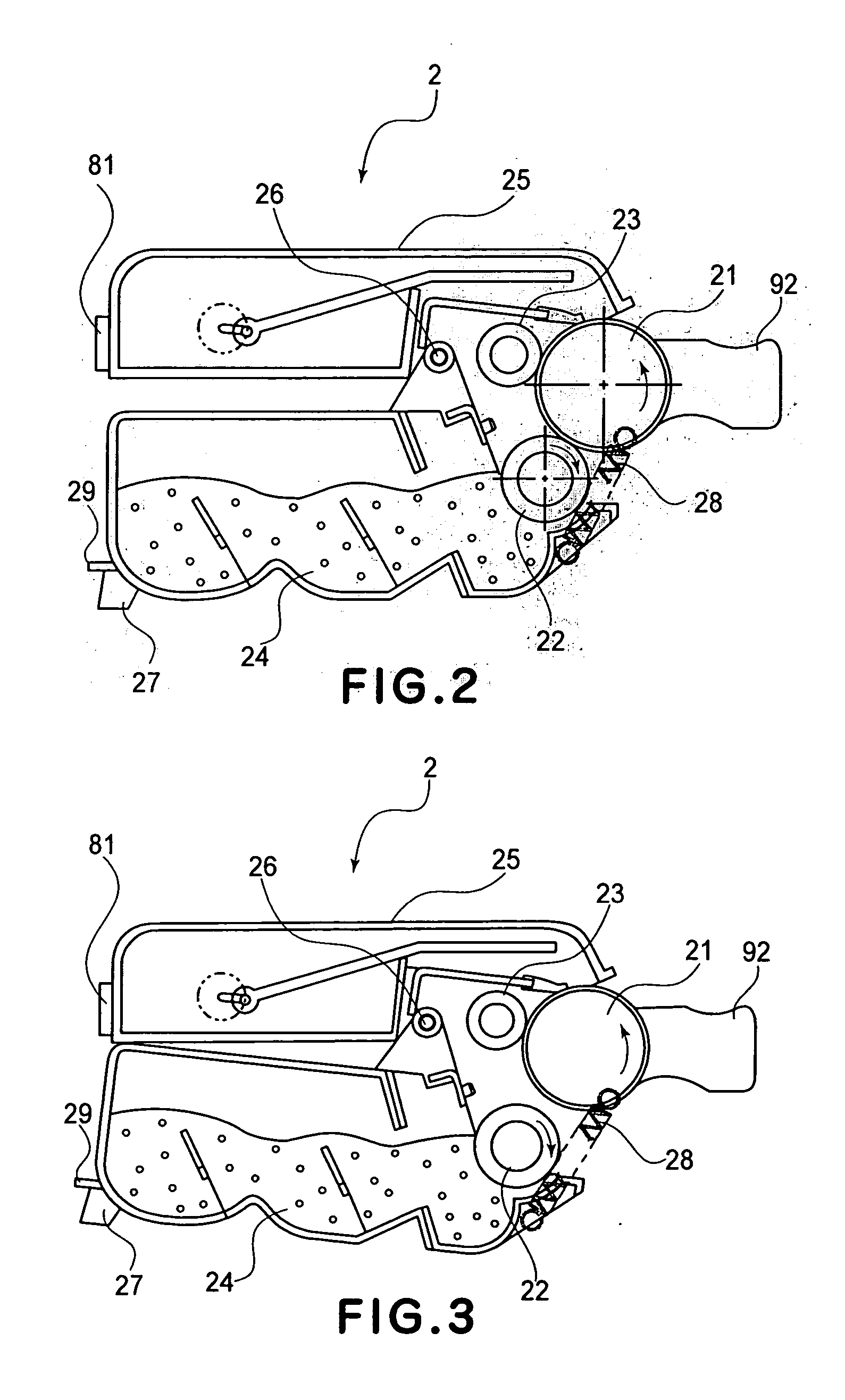
A process cartridge transportable when mounted in a main assembly of an electrophotographic image forming apparatus. The cartridge includes an electrophotographic photosensitive drum, a developing roller for developing an electrostatic latent image on the drum when in contact with the drum, a drum unit supporting the drum, a developing unit supporting the roller and connected with the drum unit for rotation between a contact position in contact with the drum and a separated position, a force receiving portion for receiving, from the main assembly, a force for moving the developing unit from the contact to the separated position, with the cartridge mounted in the main assembly, a separation member for maintaining the developing unit at a position where the developing roller and the drum are separated from each other, and a detection portion to detect the mounting of the separation member when the cartridge mounted in the main assembly.

Description

FIELD OF THE INVENTION AND RELATED ART [0001] The present invention relates to a process cartridge, and an electrophotographic image forming apparatus in which a process cartridge is removably mountable. [0002] Here, an electrophotographic image forming apparatus means an apparatus which forms an image on recording medium (for example, sheet of recording paper, a sheet for OHP, etc.), with the use of an electrophotographic image forming method. As examples of an electrophotographic image forming apparatus, an electrophotographic copying machine, an electrophotographic printer (LED printer, laser beam printer), a wordprocessor, a facsimile machine, and the like can be included. [0003] A process cartridge means a cartridge in which at least an electrophotographic photosensitive member, and a development roller are integrally disposed, and which is removably mountable in the main assembly of an electrophotographic image forming apparatus. A development roller is a processing means whic...

Claims


Application Information

Patent Timeline
Patent Type & Authority Applications(United States)
IPC IPC(8): G03G21/18
CPCG03G21/181G03G2221/1861G03G21/1825G03G15/06G03G21/18
Inventor KAWAMURA, HIROSHINITTANI, SUSUMU
Owner CANON KK
Learn More