
Pipelayer subframe and work machine with same

Inactive Publication Date: 2006-11-02
CATERPILLAR INC
View PDF18 Cites 29 Cited by
  • Summary
  • Abstract
  • Description
  • Claims
  • Application Information

AI Technical Summary

Problems solved by technology

Because of the specific application of the pipelayers, there are many components unique to the pipelayer, thereby increasing the cost of production and the number of serviceable parts needed to be stocked.
The position of the center frame on the chassis can interfere with installation of tractor components, such as an engine, into a standard-sized tractor chassis during assembly.
Thus, in order to assemble the pipelayer, a longer, modified chassis, along with modified tractor components, are used, thereby increasing the cost of production.
Moreover, the center frame attached to the chassis can obscure the field of vision for the pipelayer operator.
However, performance, can be compromised with a converted bulldozer / pipelayer.
The shorter tracks of the bulldozer can reduce the for and aft stability of the pipelayer.

Method used


Image

  • Pipelayer subframe and work machine with same
  • Pipelayer subframe and work machine with same
  • Pipelayer subframe and work machine with same

Examples


Embodiment Construction

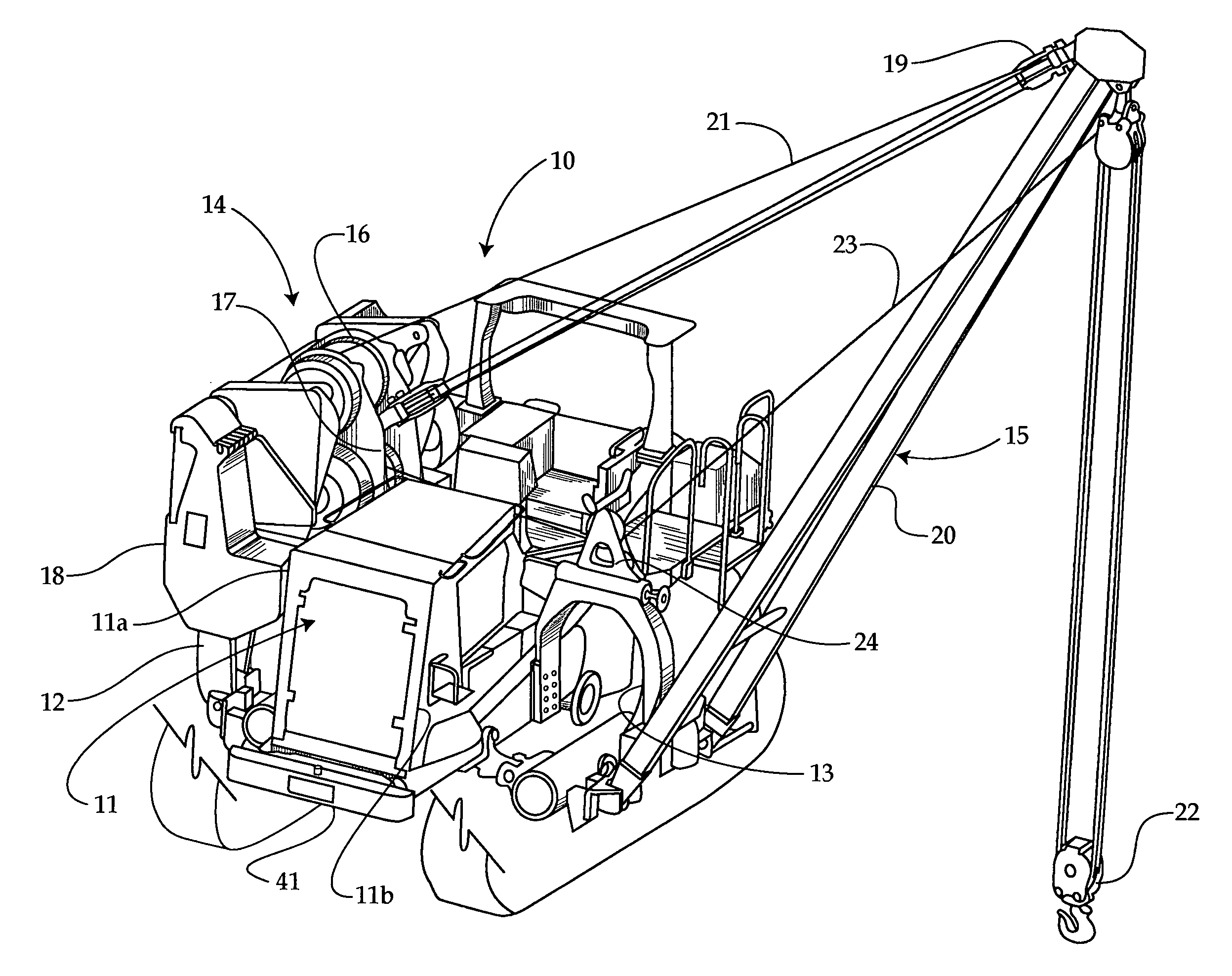
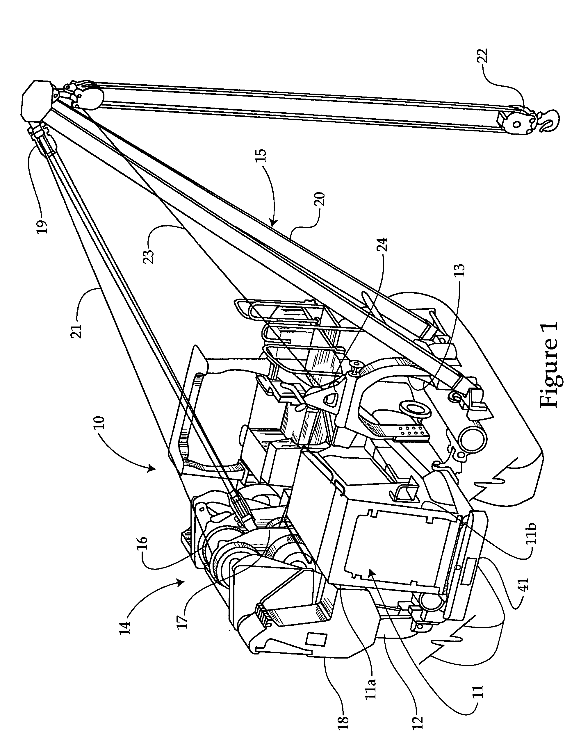
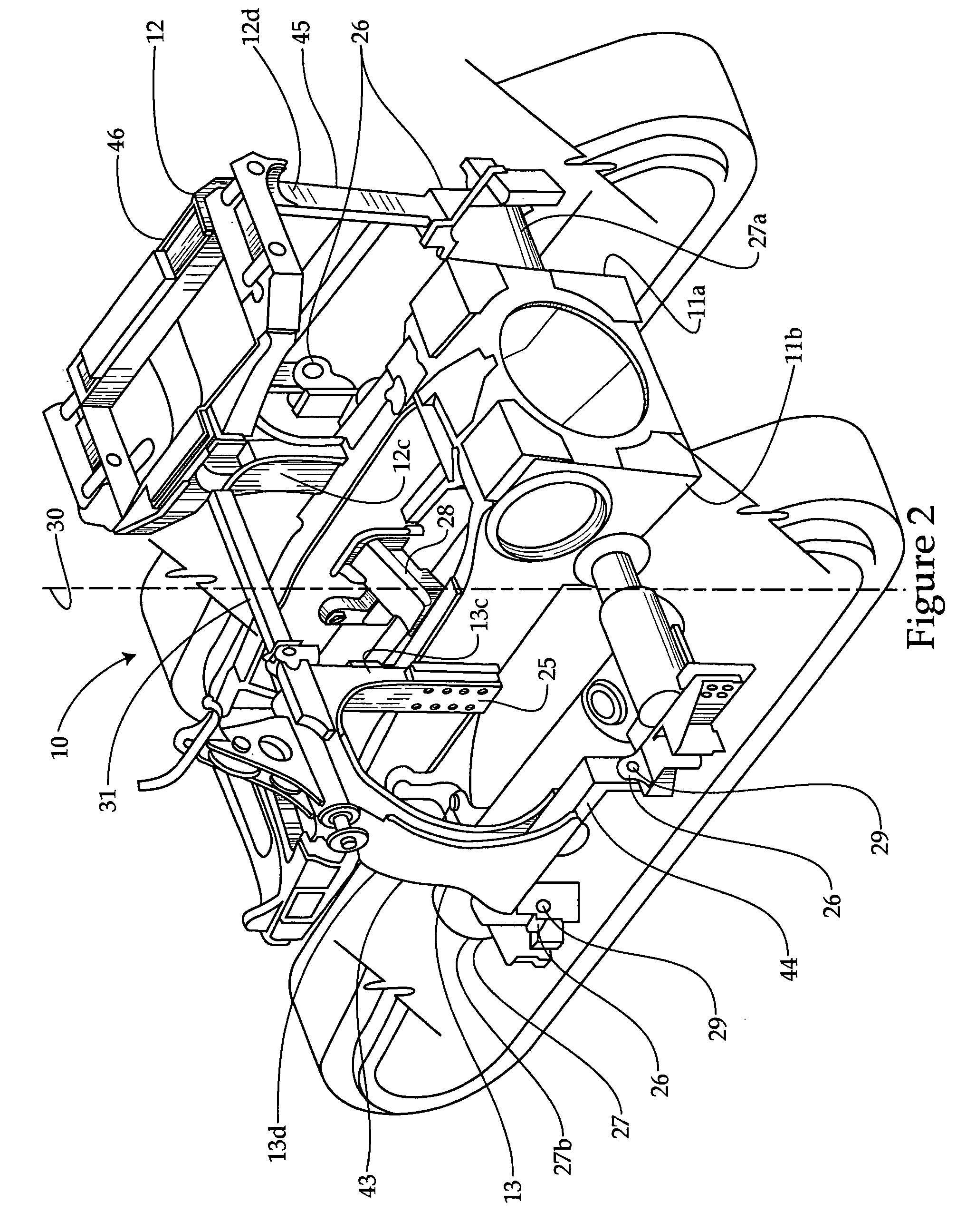
[0012] Referring to FIG. 1, there is shown a pipelayer 10, according to the present disclosure. Although the present disclosure is illustrated for the pipelayer 10, it should be appreciated that the present disclosure could apply to various track type work machines to which an implement or a portion of an implement is attached to opposite sides of the work machine. The pipelayer 10 includes a work machine chassis 11 including a first side 11a and a second side 11b. The chassis 11 is preferably a standard-bulldozer chassis 11. A first sub-frame, preferably a winch frame 12, is attached to the first side 11a of the chassis 11, and a second sub-frame, preferably a boom frame 13, is attached to a second side 11b of the chassis 11. Those skilled in the art will appreciate that the winch frame 12 also includes a counterweight frame. A conventional boom assembly 15 of the type known in the art is attached to the boom frame 13, and a counterweight 18 and a winch assembly 14 of the type know...


PUM


Abstract

In order to reduce production and maintenance costs, it is desirable that application-specific machines, such as pipelayers, include common parts with standard track-type work machines, such as a counterpart bulldozer. According to the present disclosure, a pipelayer is assembled by attaching a winch frame and a boom frame to a first and second side of a chassis, respectively. The attached boom frame and the attached winch frame are interconnected by extending a cross-bar between the boom and winch frames.

Description

TECHNICAL FIELD [0001] The present disclosure relates generally to tracked type work machines, and more specifically to a frame assembly for a pipelayer. BACKGROUND [0002] Pipelayers are unique track-type work machines used specifically in pipelaying operations, in which the pipelayer raises, lowers and carries relatively heavy pipes. Because of the specific application of the pipelayers, there are many components unique to the pipelayer, thereby increasing the cost of production and the number of serviceable parts needed to be stocked. For instance, pipelayers, such as the pipelayer described in U.S. Pat. No. 5,332,110, issued to Forsyth on Jul. 26, 1994, include a tractor chassis attached to right and left track frames. A support frame includes a boom frame that is attached to one side of the chassis and a winch frame that is attached to the other side of the chassis. The boom frame supports a boom which raises, lowers and carries the heavy pipes. The winch frame supports a winch ...

Claims


Application Information

Patent Timeline
IPC IPC(8): B60P3/12
CPCB66C23/44
Inventor DIETZ, BARRY A.SPIEGEL, FREDERICK A. IIIRICHARDSON, RICHARD G.HOEFLING, KENNETH J.ETZEL, JIM K.GREEN, CHRISTOPHER D.
Owner CATERPILLAR INC
Learn More