Accommodating intraocular lens implant

a technology of intraocular lens and implant, which is applied in the field of implantable intraocular lens, can solve the problems of inability to adjust the refractive power of the lens, the inability to bifocal intraocular lens, and the inability to adjust the refractive power thereof, and achieve the effect of simple design

Active Publication Date: 2006-11-02
ANEW IOL TECH
View PDF18 Cites 13 Cited by
  • Summary
  • Abstract
  • Description
  • Claims
  • Application Information

AI Technical Summary

Benefits of technology

[0012] Among other aspects and benefits, the new and improved intraocular lens implant of the present disclosure allows the coaxial position of the optic along the vision axis to be changed by control of the user such that the intraocular lens implant accommodates automatically. The new and improved intraocular lens implant utilizes the ciliary muscle action and the vitreous pressure of the eye to effect accommodation movement of the lens optic along the vision axis of the eye between a distant vision position to a near vision position. The new and improved intraocular lens implant is simple in design and can be folded for insertion into the eye.

Problems solved by technology

However, an anterior chamber distance (ACD) is fixed (i.e., does not accommodate), the central optic 101 is not moveable along the vision axis A of the eye, and the refractive power of the lens cannot be adjusted.
However, the anterior chamber distance (ACD) is fixed, and the refractive power thereof cannot be adjusted.
Bifocal intraocular lenses, however, suffer from the disadvantage that each bifocal image represents only about 40% of the available light and the remaining 20% of the light is lost in scatter.

Method used


Image

  • Accommodating intraocular lens implant
  • Accommodating intraocular lens implant
  • Accommodating intraocular lens implant

Examples


Embodiment Construction

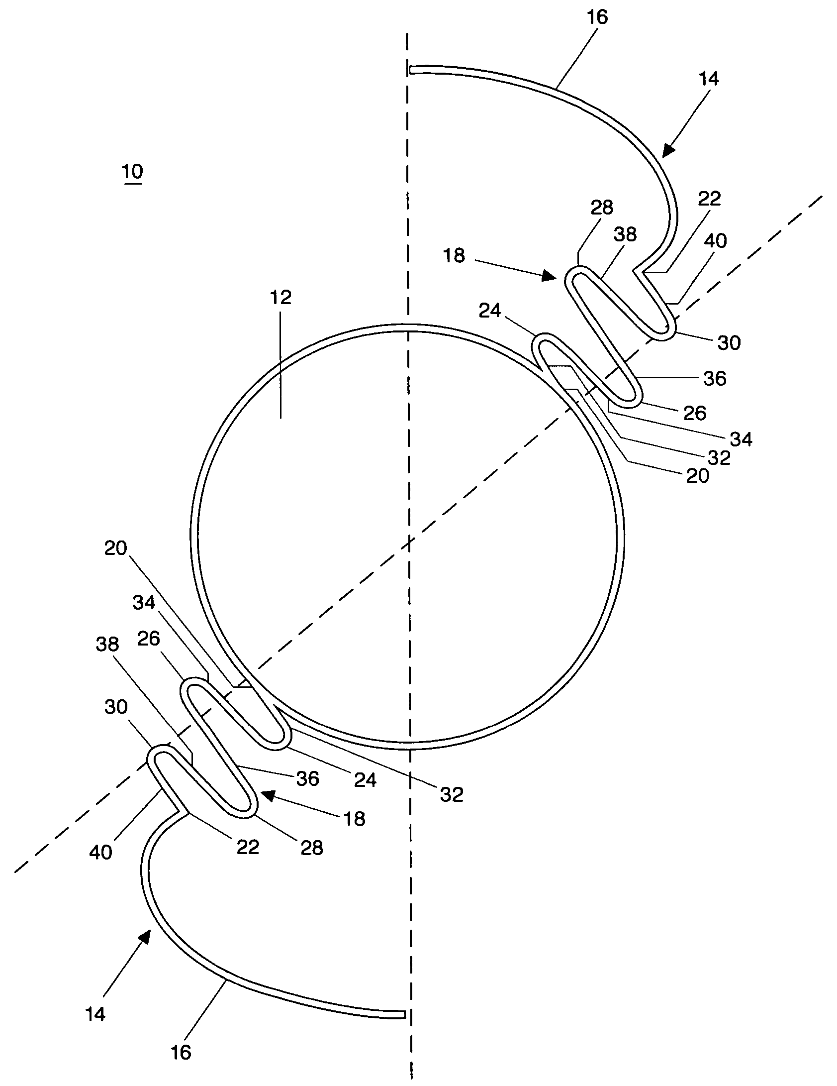
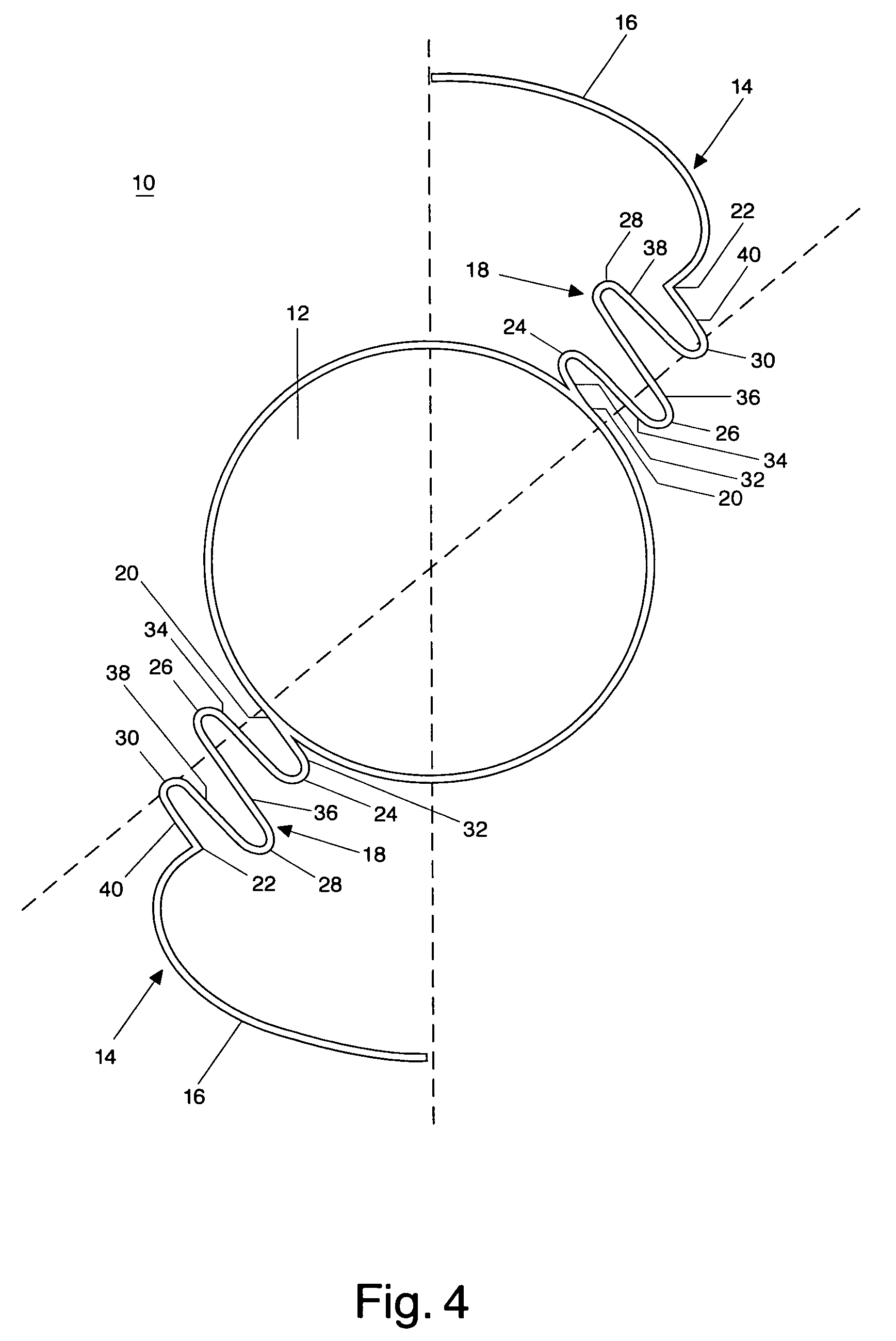
[0023] In FIGS. 4-6 of the accompanying drawings, there is shown an exemplary embodiment of an accommodating intraocular lens implant 10 according to the present disclosure for implantation in a human eye. The accommodating intraocular lens implant 10 includes an optic 12 adapted for coaxial alignment with a vision axis A of the human eye, as shown in FIG. 6, and at least one haptic 14.

[0024] The haptic 14, which is shown best in FIG. 5, includes an anchor portion 16 for receipt in a periphery of a capsular bag of the human eye, a cilairy sulcus of the human eye, or an angle of the anterior chamber of the human eye, for example. The haptic 14 also includes a sinuous portion 18 extending radially outwardly from a circumference of the optic 12 and including a proximal end 20 connected to the optic 12, a distal end 22 spaced from the optic and connected to the anchor portion 16, and at least four curves 24, 26, 28, 30 successively connected between the proximal end 20 and the distal e...


PUM


Abstract

An accommodating intraocular lens implant for implantation in a human eye, including an optic adapted for coaxial alignment with a vision axis of the human eye, and at least one haptic. The haptic includes an anchor portion for receipt in one of a periphery of a capsular bag of the human eye, a cilairy sulcus of the human eye, and an angle of the anterior chamber of the human eye, and a sinuous portion extending radially from the optic and including a proximal end connected to the optic, a distal end spaced from the optic and connected to the anchor portion, and at least four curves successively connected between the proximal end and the distal end. The sinuous portion is adapted to flex upon ciliary muscle action to move the optic along the vision axis and allow the intraocular lens implant to automatically accommodate.

Description

FIELD OF THE DISCLOSURE [0001] The present disclosure relates to implantable intraocular lenses. Even more particularly, the present disclosure relates to a new and improved accommodating intraocular lens implant having an optic that can move forward and backward along a visual axis of an eye in response to vitreous pressure and contraction and relaxation of the ciliary muscle. BACKGROUND OF THE DISCLOSURE [0002] The crystalline lens is a transparent structure that focuses light in the human eye. Opacification of the lens known as cataract formation is a common cause of poor vision in the elderly, and can be corrected surgically. [0003] Modern cataract surgery is performed by manual extracapsular cataract extraction, or by phacoemulsification. In both operations an opening is made in the anterior capsule to allow removal of the lens contents. The capsular bag remnant, however, is left in situ to provide support for an intraocular lens implant which is inserted following removal of t...

Claims


Application Information

Patent Timeline
Patent Type & Authority Applications(United States)
IPC IPC(8): A61F2/16
CPCA61F2/1629A61F2002/1686A61F2002/1683
Inventor KOCH, PAUL S.
Owner ANEW IOL TECH
Why Eureka
Try Eureka