Ultrasonic Aerosol Generator

a generator and ultrasonic technology, applied in the direction of liquid spraying apparatus, spraying apparatus, medical atomisers, etc., can solve the problems formation of fine aerosol droplets, and humidifiers that are not designed for direct inhalation of mist, etc., to achieve stable formulation and low cost

Inactive Publication Date: 2006-11-09
PULMATRIX
View PDF32 Cites 77 Cited by
  • Summary
  • Abstract
  • Description
  • Claims
  • Application Information

AI Technical Summary

Benefits of technology

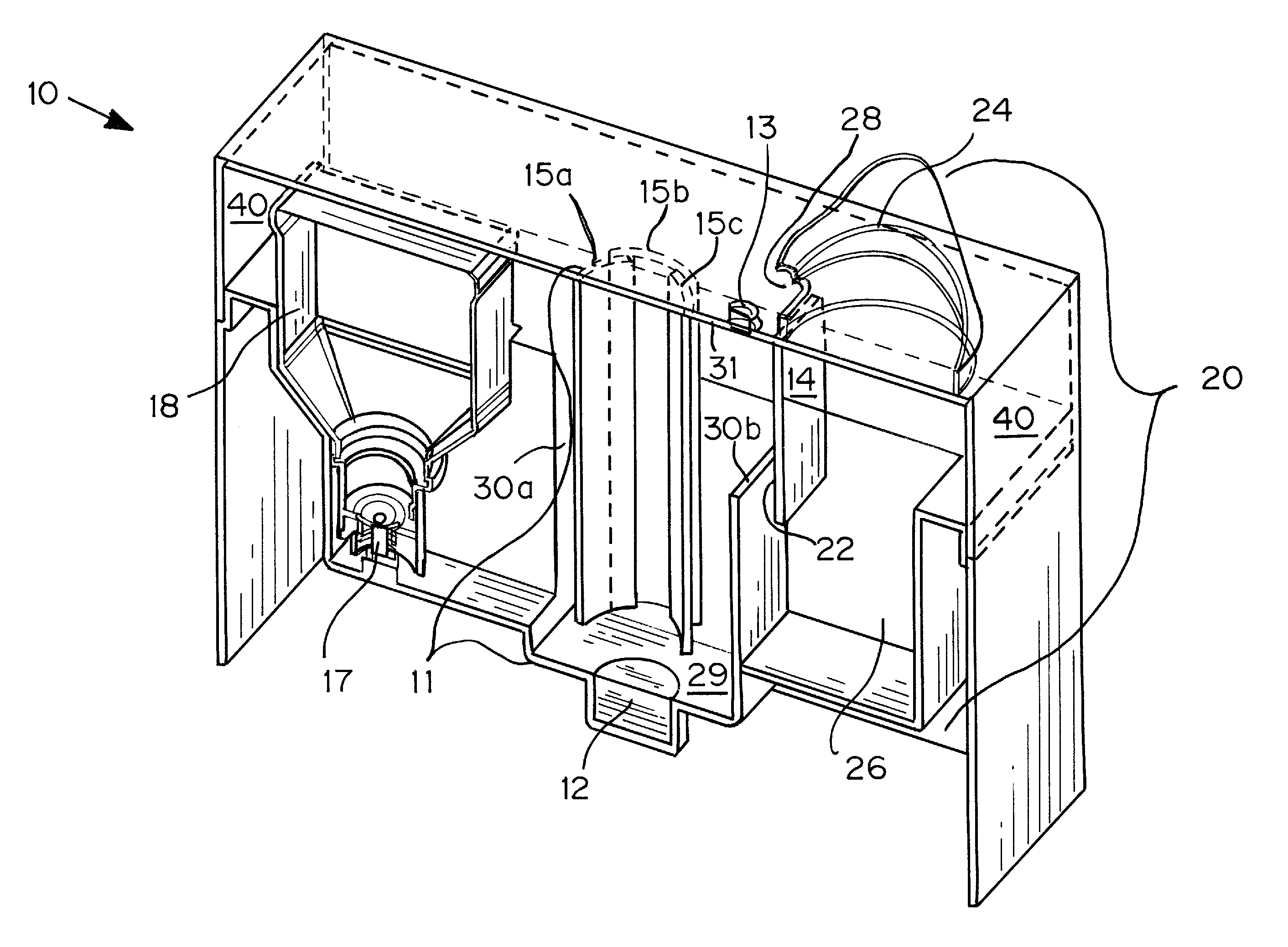
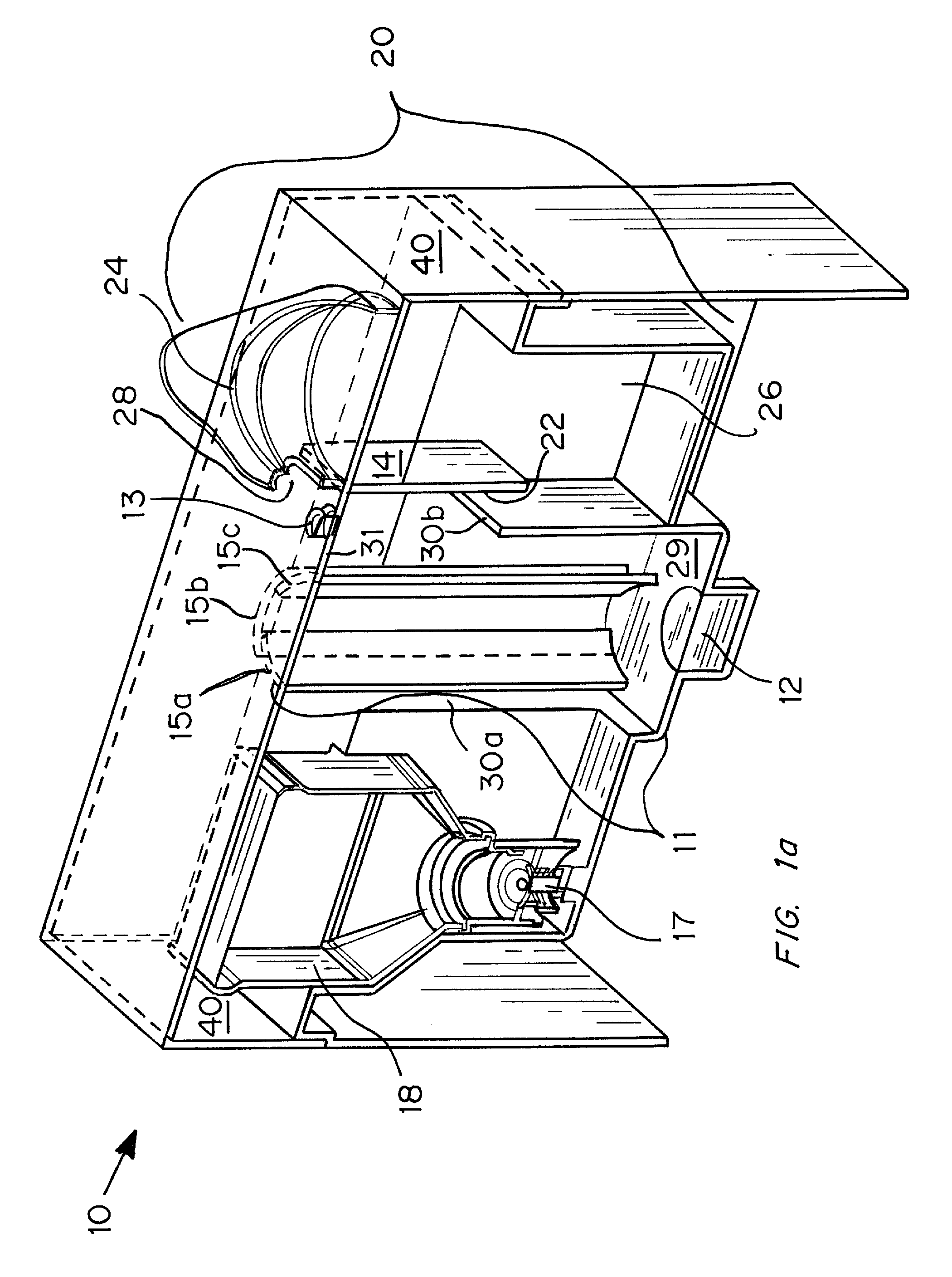
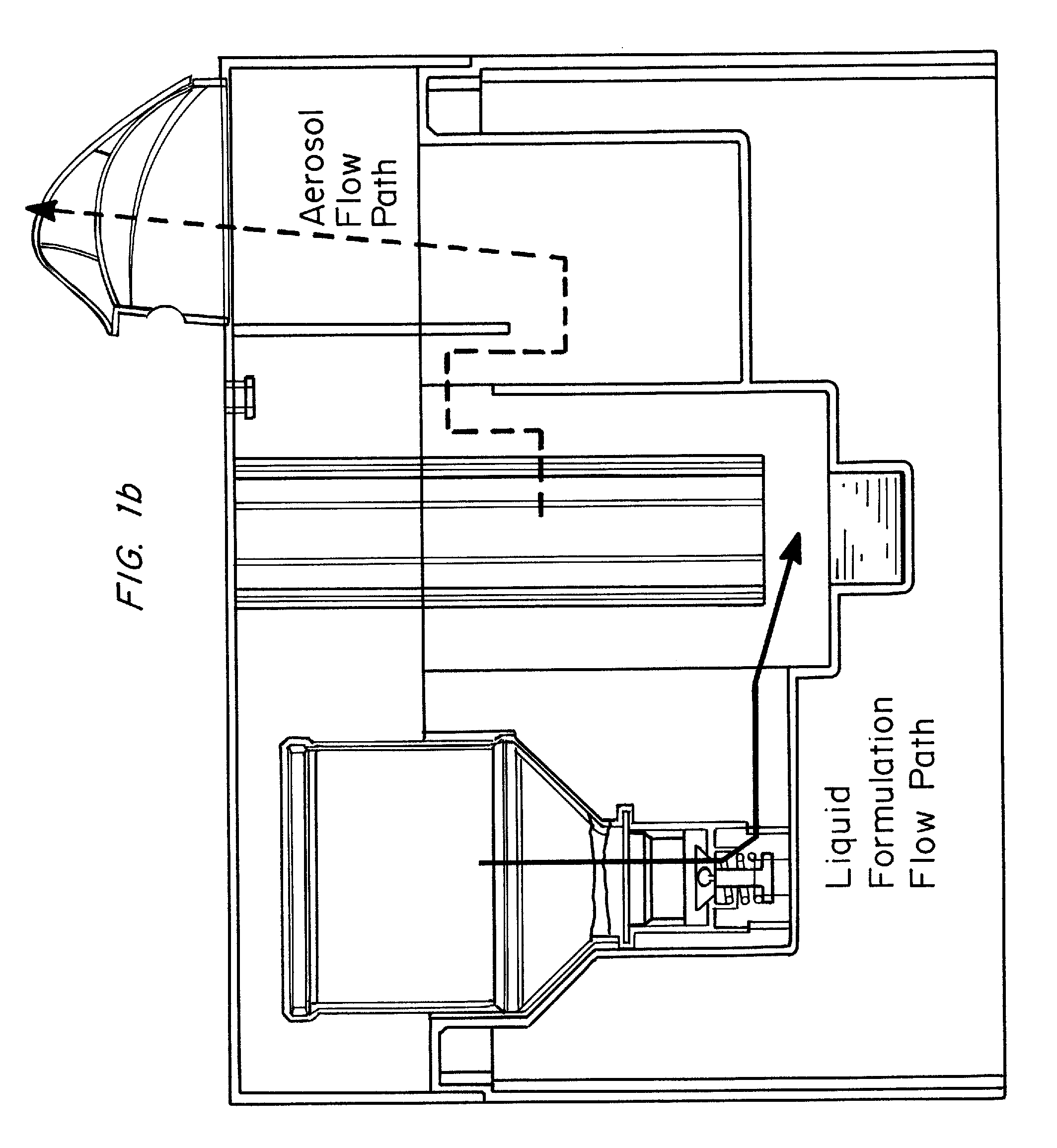
[0008] An ultrasonic aerosol generator for delivering a liquid formulation in an aerosolized form at a high output rate of greater than 0.5 mL / minute, preferably greater than 1.0 mL / minute, and with diameters in a respirable size range and methods of using this device are described herein. The ultrasonic aerosol generator (10) contains at least (a) a liquid reservoir / aerosolization chamber (11), (b) a piezoelectric engine (12), (c) a relief aperture (13), and (d) an aerosol delivery element (20). Preferably the aerosolized particles that are delivered to the user through the aerosol delivery element have an average aerodynamic diameter of between 1 and 20 μm, more preferably between 1 and 10 μm, and most preferably between 1 and 5 μm. Optionally, the ultrasonic aerosol generator is designed to deliver more than one formulation simultaneously, preferably a low cost and / or stable formulation is administered simultaneously with a more expensive and / or labile formulation. In the preferred embodiment, the ultrasonic aerosol generator is a hand-held device designed for a single user.

Problems solved by technology

Some ultrasonic nebulizers contain a vibrating screen which is in contact with the drug solution and results in the formation of fine aerosol droplets.
The vibrating horn forces the drug solution through the stationary screen, resulting in the formation of fine aerosol droplets.
However, these humidifiers are not designed for direct inhalation of the mist, nor are they designed to produce aerosol with particles in the respirable size range.

Method used


Image

  • Ultrasonic Aerosol Generator
  • Ultrasonic Aerosol Generator
  • Ultrasonic Aerosol Generator

Examples


example

[0073] Two devices corresponding to the configurations depicted in FIGS. 3 and 2 respectively (labeled “Devices A and B”, respectively, in FIGS. 5 and 6) were tested and compared with commercially available ultrasonic nebulizers, jet nebulizers, and ultrasonic humidifiers. Two different ultrasonic nebulizers were tested (AERONEB® Go Model 7000 (AeroGen, Inc.) and OMRON® MICROAIRE® Model NE-U22V, labeled A and B, respectively, in FIGS. 5 and 6) four different jet nebulizers were tested (Hudson RCI Micro Mist Model 1882; Invacare SIDESTREAM® Model MS2400 (Medic-Aid Limited Corp., United Kingdom); RESPIRONICS® VENTSTREAM® Model PL273, and OMRON® CompAir Elite Model NE-C21V; labeled A, B, C, and D, respectively, in FIGS. 5 and 6), and three different ultrasonic humidifiers were tested (WALGREENS® Model 700, VICKS® Model V5100N and SUNBEAM® Model 697-6, labeled A, B and C, respectively, in FIGS. 5 and 6) to determine their aerosol output rates and average aerosolized particle size. All c...


PUM


Abstract

An ultrasonic aerosol generator for delivering a liquid formulation in an aerosolized form at a high output rate of greater than 0.5 mL / minute, preferably greater than 1.0 mL / minute, and with diameters in a respirable size range, methods of using this device and kits including the device are described herein. The ultrasonic aerosol generator (10) contains at least (a) a liquid reservoir / aerosolization chamber (11), (b) a piezoelectric engine (12), (c) a relief aperture (13), and (d) an aerosol delivery element (20). Preferably the aerosolized particles that are delivered to the user through the aerosol delivery element have an average aerodynamic diameter of between 1 and 20 μm, more preferably between 1 and 10 μm, and most preferably between 1 and 5 μm. Optionally, the ultrasonic aerosol generator is designed to deliver more than one formulation simultaneously, preferably a low cost and / or stable formulation is administered simultaneously with a more expensive and / or labile formulation. In the preferred embodiment, the ultrasonic aerosol generator is a hand-held device designed for a single user.

Description

CROSS-REFERENCE TO RELATED APPLICATIONS [0001] This application claims priority to U.S. Ser. No. 60 / 678,085, filed May 5, 2005 and U.S. Ser. No. 60 / 715,670, filed Sep. 9, 2005.FIELD OF THE INVENTION [0002] The present invention is in the field of improved devices for aerosolizing and administering liquid formulations to end users. BACKGROUND OF THE INVENTION [0003] In some applications there is a need to deliver high quantity of aerosolized formulations in a respirable particle size range over a short period of time, for example, for delivering active agents to prevent the spread of airborne respiratory infectious diseases (also known as “ARIDs”), or for treating cystic fibrosis. The currently available aerosol generators include nebulizers and humidifiers. [0004] Liquid nebulization is a common method of medical aerosol generation. There are two types of nebulizers, jet and ultrasonic. The nebulizers are typically small, hand-held devices. Jet nebulizers use the Venturi principle t...

Claims


Application Information

Patent Timeline
Patent Type & Authority Applications(United States)
IPC IPC(8): A61M11/00
CPCB05B17/0615A61M15/0085
Inventor DEHAAN, WESLEY H.WATANABE, WIWIK S.
Owner PULMATRIX
Why Eureka
Try Eureka