Method and apparatus for displaying images on reflective surfaces

a technology of reflective surfaces and displays, applied in the field of optical display systems, can solve the problems of high-resolution displays, high-cost control circuitry, and direct retinal projection, and achieve the effect of low-cost and simplified design

Inactive Publication Date: 2006-11-09
GRAND IDEA STUDO
View PDF2 Cites 57 Cited by
  • Summary
  • Abstract
  • Description
  • Claims
  • Application Information

AI Technical Summary

Benefits of technology

[0005] This current invention takes advantage of the optical characteristics of the lens already in place on a head-mounted unit (e.g., goggles) or eyeglasses, simplifying the design and allowing the invention to be used in a wide variety of consumer, low-cost applications. A reflective image display (RID) according to the present invention is designed to be an implant for virtually any head-worn device, protective or otherwise, that has a lens in the vicinity of the eyes. In preferred implementations, the RID comprises a small light-emitting display (LED) module or other backlit display technology supported by electronic circuitry to display information relevant to the viewer by reflecting the lit image from the inside of the lens. The LED or other display is mounted such that a vertical, horizontal, or a combination of vertical and horizontal mirror image is seen by the viewer. The viewed image is typically magnified by the curvature of the lens and appears to float ‘in thin air’ on the outer side of the lens.
[0006] An advantage of the RID invention is its low-cost method of displaying information in any glasses or head-mounted unit.

Problems solved by technology

Currently existing technologies, such as retinal direct projection, typically make use of expensive optics and mirrors and require high-resolution displays and expensive control circuitry.

Method used


Image

  • Method and apparatus for displaying images on reflective surfaces
  • Method and apparatus for displaying images on reflective surfaces
  • Method and apparatus for displaying images on reflective surfaces

Examples


Embodiment Construction

[0016] Although described herein with reference to headgear, and as useful when implemented with regard to projecting optical displays thereon, the systems and methods described below are applicable to any projection system in which the following systems and methods can be applied.

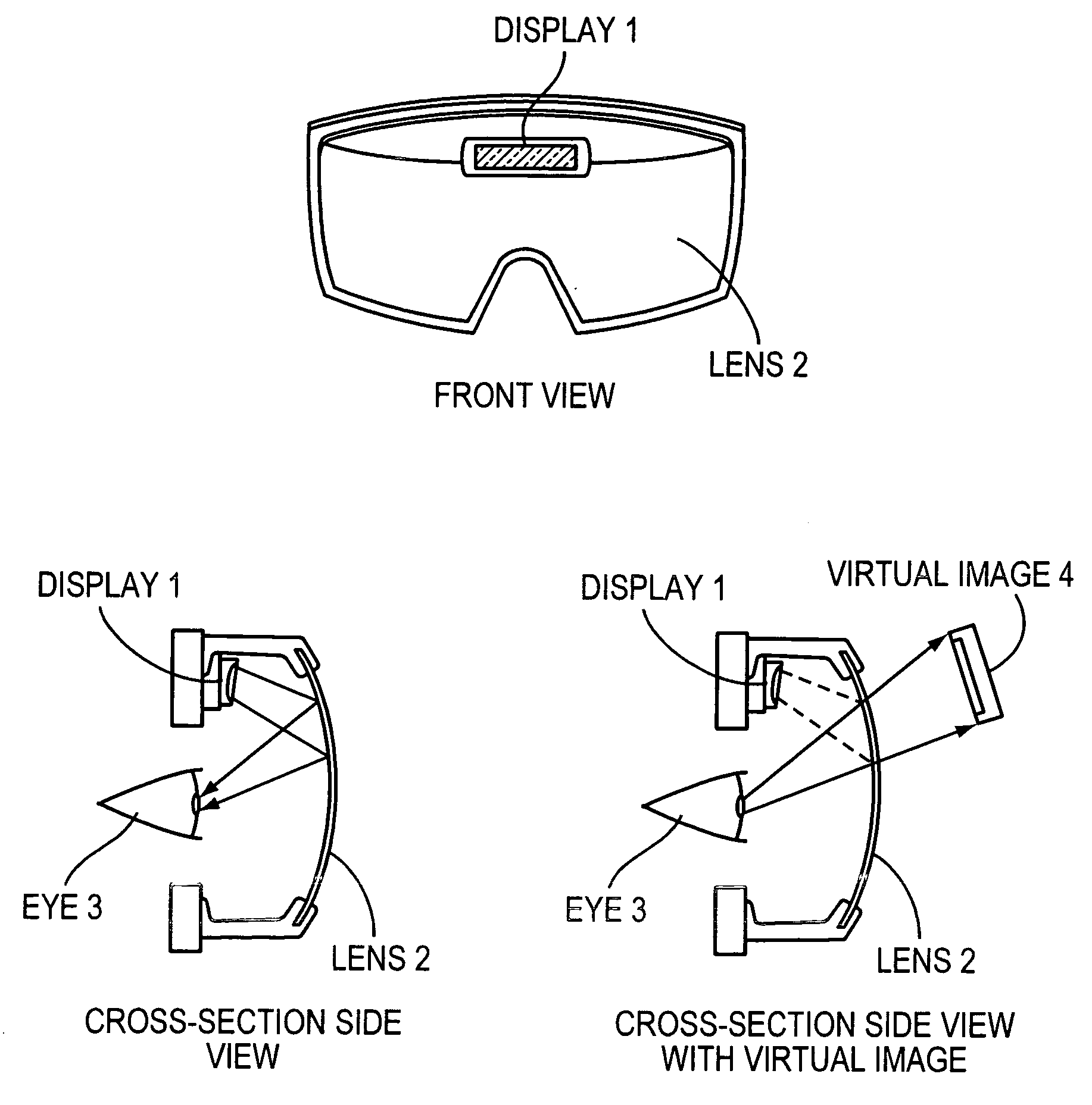
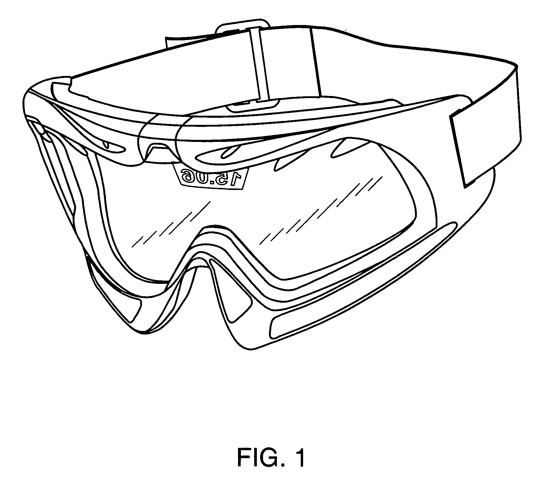
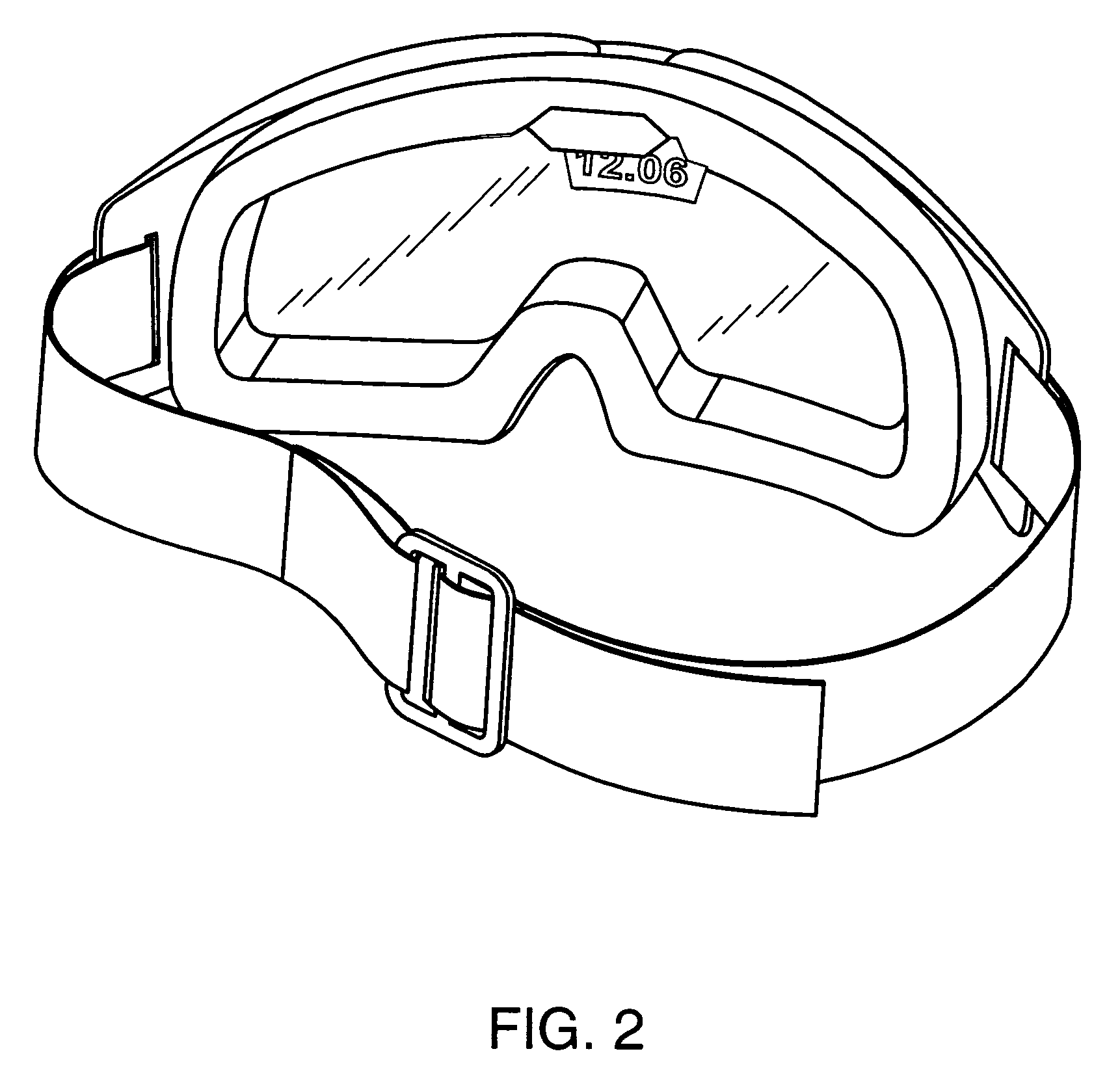
[0017] In one embodiment, a RID in accordance with the invention mounts inside snowboarding or ski goggles and creates a visual display that utilizes the reflective quality of the goggle lens, producing an image which appears to float in space in front of the eyes. The RID can be used, for example, to display information such as the time of day or data (temperature, altitude, or number of runs) collected from sensors inside or outside the goggles. All user controls are desirably operated by a single button on the outside of the goggle that can be easily accessed without removing gloves or outer clothing. When enabled with a single pushbutton switch, the display illuminates to show, for example, the curren...


PUM


Abstract

A head mounted display (HMD) is worn on a user's head for displaying an image. A HMD is a personal see-through device designed to view still or video images or data that nonetheless permits the user to view his surroundings.

Description

RELATED APPLICATION [0001] This application claims the benefit of U.S. provisional patent application Ser. No. 60 / 677,130, filed on May 3, 2005, the entire disclosure of which is incorporated herein in its entirety.TECHNICAL FIELD [0002] This invention relates to providing an optical display system, and more particularly to head-mounted displays. BACKGROUND INFORMATION [0003] A head mounted display (HMD) is worn on a user's head for displaying an image. Generally, HMDs are configured as helmets or goggles, depending on how the display is to be worn. A HMD is a personal see-through device designed to view still or video images or data that nonetheless permits the user to view his surroundings. [0004] The critical component of any HMD is the optical display system. Currently existing technologies, such as retinal direct projection, typically make use of expensive optics and mirrors and require high-resolution displays and expensive control circuitry. SUMMARY [0005] This current invent...

Claims


Application Information

Patent Timeline
Patent Type & Authority Applications(United States)
IPC IPC(8): G02C1/00
CPCG02B27/017G02B2027/0178G02B2027/011G02B27/0172
Inventor GRAND, JOSEPH B.MORELOCK, DAVID M.MANALO, GIL DAVIDCRUZ, RICARDO ANTONIO
Owner GRAND IDEA STUDO
Why Eureka
Try Eureka