Data processing apparatus and parameter generating apparatus applied to surround system

a data processing apparatus and parameter generating technology, applied in computing, instruments, stereophonic arrangments, etc., can solve the problems of blurred sound image, complicated calculation, user's complex operation, etc., and achieve the effect of simple operation

Inactive Publication Date: 2006-11-09
YAMAHA CORP
View PDF5 Cites 13 Cited by
  • Summary
  • Abstract
  • Description
  • Claims
  • Application Information

AI Technical Summary

Benefits of technology

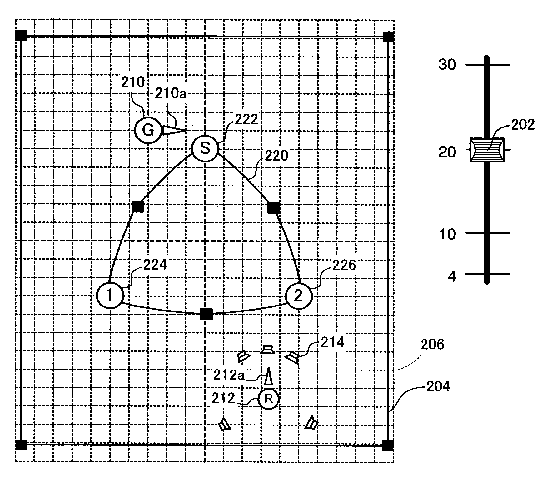
[0019] According to the second feature, the size of the acoustic space and the position of the sound emitting point and the sound receiving point are re-specified in response to the change in the scale such that the acoustic space image, the sound emitting point image and the sound receiving point image are displayed at the same position as the position where they were displayed in the previous scale. In other words, a user's operation for changing scale also causes automatic refresh of various settings of the acoustic space. In addition, the second feature in which the speaker image is displayed on the display unit enables the user to intuitively grasp, on the screen, the relation between an assumed listening room and the acoustic space.
[0025] According to the third feature, in response to the instruction for transferring one of the selected operational elements, the transfer state for all the selected operational elements is determined on the basis of the instruction of transfer and the limited transfer manner. As a result, the third feature enables the user to simultaneously modify the arrangement of the elements in the acoustic space with a simple operation.

Problems solved by technology

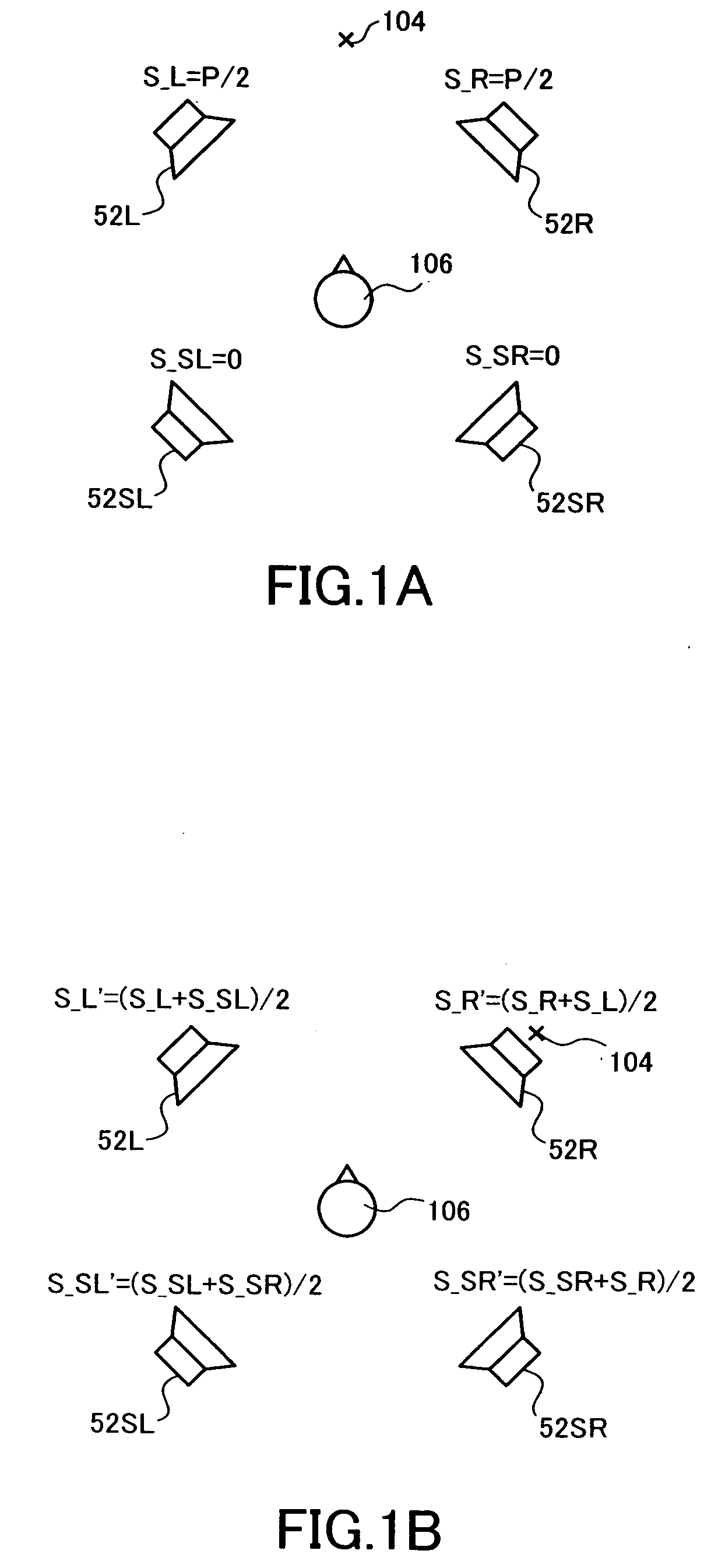
Although the above sound pressure brings agreement between the center of the sound image and the orientation of the speaker 52R and makes the total sum of the sound pressure agree with “P”, there still exists a problem that the sound image sounds blurred because a sound that simulates the sound emitting point 104 is separated to be output from the three speakers.
In addition, there is another problem that complicated calculation is required to rotate a sound field by use of the art disclosed in Japanese Patent Laid-Open Publication No. 2003-271135 after generation of multi-channel signals by use of the arts disclosed in Japanese Patent Laid-Open Publication No. 2004-212797 and Japanese Patent Laid-Open Publication No. 2004-312109.
In such cases, however, on using the arts disclosed in Japanese Patent Laid-Open Publication No. 2004-312109 and U.S. Pat. No. 5,636,283, a user is required quite complicated operations such as specifying the size of the acoustic space and the position of the sound emitting point 104 and the sound receiving point 106 individually.

Method used


Image

  • Data processing apparatus and parameter generating apparatus applied to surround system
  • Data processing apparatus and parameter generating apparatus applied to surround system
  • Data processing apparatus and parameter generating apparatus applied to surround system

Examples


Embodiment Construction

1. Overview of Embodiment

1.1 Correlation between Position of Elements and Sound

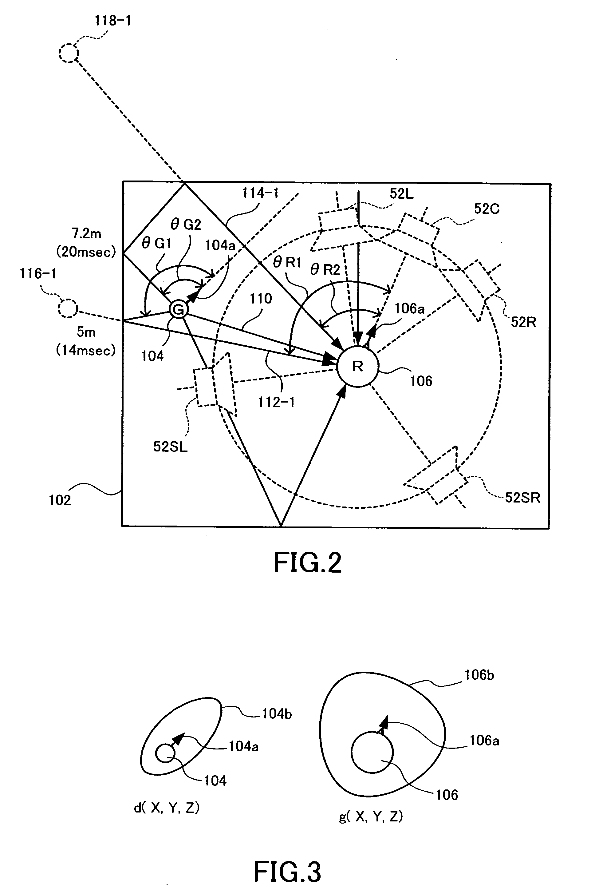
[0055] Assume that, in FIG. 2, a sound emitting point 104 and a sound receiving point 106 are placed in a rectangular parallelepipedic acoustic space 102. A direct sound reaches the sound receiving point 106 from the sound emitting point 104 along a sound path (a path along which sounds propagate) 110. Along a sound path 112-1, in addition, a first reflected sound (a sound reflected off a wall surface of the acoustic space 102 only once) reaches the sound receiving point 106. The total number of sound paths for first reflected sounds is six, that is to say, the same number as that of the wall surfaces which form the rectangular parallelepipedic acoustic space 102. In addition to the sound path 112-1, namely, there are five more sound paths (not shown).

[0056] In addition, a second reflected sound travels along a sound path 114-1. The total number of sound paths for second reflected sounds is eighteen....


PUM


Abstract

Calculation is performed for sound paths 112-1, 114-1 along which sounds emitted from a sound emitting point 104 in an acoustic space 102 are reflected and delivered to a sound receiving point 106. By the calculation, entering angles θR1, θR2 by which the sound paths enter the front side 106a of the sound receiving point 106 are obtained. Calculation is then performed to obtain angles by which respective speakers 52C, 52L, 52R, 52SR, 52SL of a 5.1 surround system are arranged in a listening room, with the front side 106a of the sound receiving point 106 centered thereon. Audio signals on the respective sound paths are distributed among channels for any two speakers. Consequently, sharp localization of sound images is achieved, requiring less calculation in simulating acoustic characteristics of the acoustic space 102 in which the sound emitting point 104 for emitting sounds and the sound receiving point 106 for receiving the sounds are placed.

Description

BACKGROUND OF THE INVENTION [0001] 1. Field of the Invention [0002] The present invention relates to a data processing apparatus and a parameter generating apparatus suitable for use in creating audio sources to be reproduced on a surround system. The present invention also relates to a computer program applied to these apparatuses. [0003] 2. Description of the Related Art [0004] Assume that a sound emitting point at which a sound is emitted and a sound receiving point at which the sound is received are placed in an acoustic space such as a room having a rectangular parallelepiped shape. The sound receiving point is a human, microphone or the like. In this case, sounds emitted from the sound emitting point reflect on various parts of the acoustic space before reaching the sound receiving point. Disclosed in Japanese Patent Laid-Open Publication No. 2004-212797 and Japanese Patent Laid-Open Publication No. 2004-312109 are apparatuses for simulating such propagation of sounds to the s...

Claims


Application Information

Patent Timeline
Patent Type & Authority Applications(United States)
IPC IPC(8): H04R5/00
CPCH04S7/302H04S2400/13H04S7/40
Inventor KITAYAMA, TORUTAMIYA, KENICHIKUSHIDA, KOJIKONDOU, MASAO
Owner YAMAHA CORP
Why Eureka
Try Eureka