Color fringe desaturation for electronic imagers

Inactive Publication Date: 2006-11-09
MONUMENT PEAK VENTURES LLC
View PDF5 Cites 49 Cited by
  • Summary
  • Abstract
  • Description
  • Claims
  • Application Information

AI Technical Summary

Benefits of technology

[0015] An advantage of the present invention is the ability to detect and correct or hide color fringes without producing image artifacts. A furt

Problems solved by technology

The problem is common around backlit trees or around the perimeter of specular reflections in jewelry or silverware.
These pat

Method used


Image

  • Color fringe desaturation for electronic imagers
  • Color fringe desaturation for electronic imagers
  • Color fringe desaturation for electronic imagers

Examples


Embodiment Construction

[0034] As used herein the term “saturation” has two meanings. Pixel values can be saturated because too much light has fallen on the pixel and the response reaches a maximum value or the pixel output becomes too non-linear to use. Saturation can also mean a color that is very pure. In this case a completely color-desaturated area is neutral and a very color-saturated area contains high values for one or two system primaries. The term “saturation” by itself will describe pixel values that are at the maximum value. The terms “color-saturation” or “color-desaturation” will be used to describe pure colors or colors at or near neutral gray.

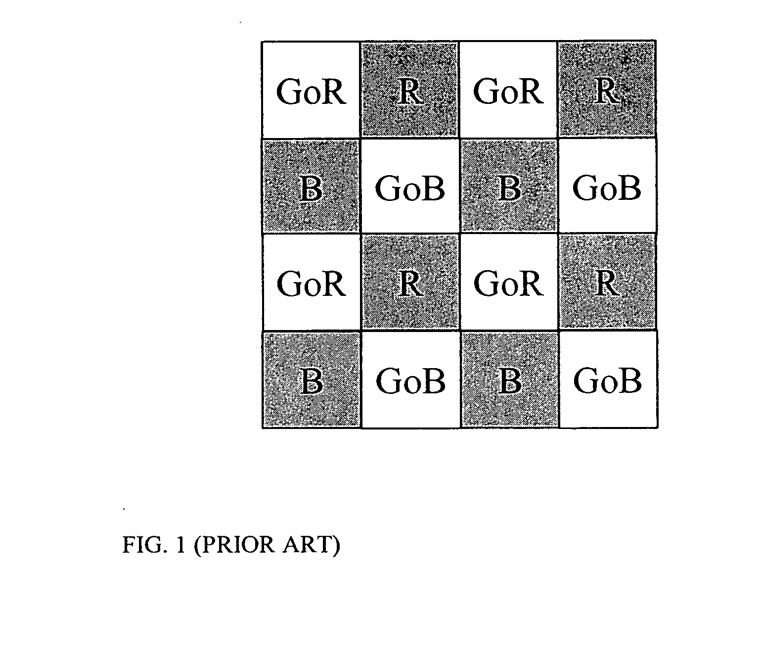
[0035] The preferred embodiment of the present invention starts with a color image. Digital cameras typically produce images from a single imager with a color filter array (CFA). The pattern in FIG. 1 is an example of a prior art Bayer CFA pattern. An imager with this pattern has two green pixels, a red pixel, and a blue pixel in every 2 by 2 block of...


PUM


Abstract

A method for correcting colored fringe artifacts in a region of an image around saturated pixels captured by an electronic imager associated with a color filter array, includes providing a threshold map of the image based on thresholding one or more color channels with a common or separate threshold value for each color channel; providing a first edge map by dilating the threshold map as a function of the color fringe width, producing a first dilated threshold map and subtracting the threshold map from the first dilated threshold map; and color-desaturating image pixels that correspond to the first edge map.

Description

FIELD OF THE INVENTION [0001] The invention relates generally to the field of digital image processing, and in particular to the correction of color shifts or fringe artifacts that occur when very light areas are next to dark areas. BACKGROUND OF THE INVENTION [0002] Many electronic imagers produce a colored fringe around very bright areas in the image. The fringe tends to be magenta or blue although the fringe color may not be limited to these colors. Bright color fringes are particularly prevalent and noticeable in areas where the saturated area is surrounded by a dark area. The problem is common around backlit trees or around the perimeter of specular reflections in jewelry or silverware. The cause is believed to be related to cross-talk due to light piping in the array or due to ray angle. [0003] Cross-talk due to ray angle occurs when a light ray falls on the imager surface at an angle, passes through a CFA patch, and falls on an adjacent pixel associated with a different color...

Claims


Application Information

Patent Timeline
IPC IPC(8): G06K9/00
CPCH04N9/646G06T5/30G06T7/0085G06T5/001G06T2207/10024G06T2207/20148H04N1/58G06T7/0091G06T7/13G06T7/155G06T7/136
Inventor PALUM, RUSSELL J.PILLMAN, BRUCE H.LARSEN, LYNN V.
Owner MONUMENT PEAK VENTURES LLC
Why Eureka
Try Eureka