
Data transmission method with lower probability of erroneous rejection of data

a data transmission and probability technology, applied in the field of data transmission methods, can solve the problems of mobile stations incorrectly believing, transmission errors, filtering that cannot be performed in the physical layer, etc., and achieve the effect of reducing the probability of false alarm detection and increasing the probability of detecting false alarm

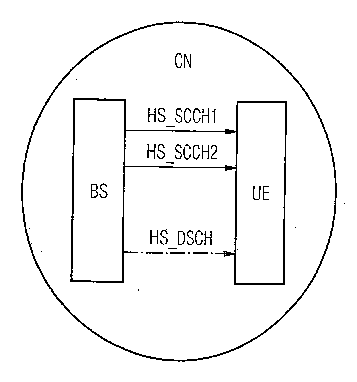
Active Publication Date: 2006-11-09
SIEMENS AG
View PDF5 Cites 6 Cited by
  • Summary
  • Abstract
  • Description
  • Claims
  • Application Information

AI Technical Summary

Benefits of technology

"The present invention proposes a method for reducing errors in data transmission in a communication network. The method involves analyzing control information and generating an overall decision parameter based on the analysis. This decision parameter is used to determine whether data should be rejected or processed further. The method also allows the terminal to listen on specific control channels and reduces the computing effort in the terminal. Additionally, the invention addresses the issue of false alarms in the communication network and proposes a consistency checking mechanism to prevent them. The technical effects of the invention include reducing errors in data transmission, reducing computing effort in the terminal, and preventing false alarms."

Problems solved by technology

Since the inconsistent control information itself is not passed on to higher layers since it is only needed in the physical layer, such filtering can only be performed in the physical layer.
Errors in transmission can now mean that the mobile station incorrectly believes that it has to receive 15 codes.
The disadvantage of this is that data can be rejected incorrectly.

Method used


Image

  • Data transmission method with lower probability of erroneous rejection of data
  • Data transmission method with lower probability of erroneous rejection of data

Examples


Embodiment Construction

[0037] Reference will now be made in detail to the preferred embodiments of the present invention, examples of which are illustrated in the accompanying drawings, wherein like reference numerals refer to like elements throughout.

[0038] Before the figures are presented in detail an initial explanation will be provided for a plurality of terms used:

[0039] A communications system or communication network is to be seen as a structure for the exchange of data. This can for example involve a cellular mobile radio network, such as the GSM (Global System of Mobile Communications) or the UMTS (Universal Mobile Telecommunications System) network. A communication network comprises at least two connection nodes, which means that this term also covers point-to-point connections.

[0040] Terminals and base stations are generally provided in a communication system, these being connected to each other via a radio interface. In UMTS the communication system or radio transmission network at least fe...


PUM


Abstract

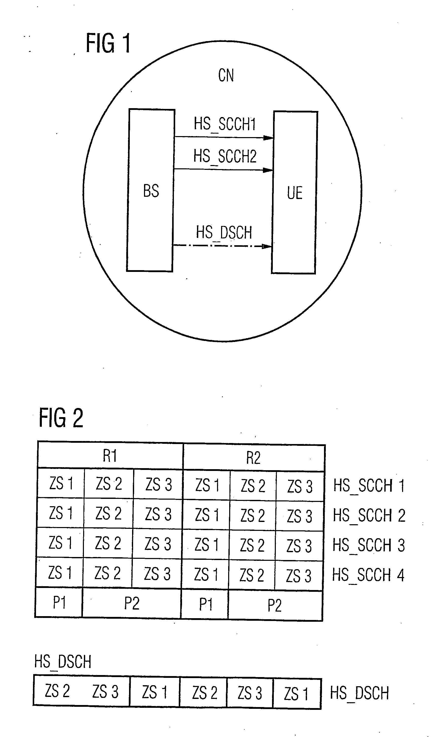
A method transmits data between a base station and a terminal in a communication system. According to said method, data is transmitted subdivided into time segments (Zs,R) from the base station (HS-DSCH) that is jointly used bye several terminals via the base station informs the terminals, and the base station informs the terminal via one of at least two control channels method encompasses the following: the at least two control channels (HS-SCCH1, HS-SCCH2) are monitored by the terminal; the terminal receives the piece of control information on a first of the at least two control channels (HS-SCCH1) within a first time segment (ZS1, R1); an individual decision parameter is generated for each of the parts (P1, P2) of control information based on the content of the respective part (P1, P2) of control information: an overall decision parameter is determined based on the individual decision parameters; data received on the data channel (HS-DSCH) and the piece of information received on the control channel (HS-SCCH1) are rejected in accordance with the overall decision parameter.

Description

CROSS REFERENCE TO RELATED APPLICATIONS [0001] This application is based on and hereby claims priority to PCT Application No. PCT / EP2004 / 052148 filed on Sep. 13, 2004 and German Application No. 10345638.4 filed on Sep. 29, 2003, the contents of which are hereby incorporated by reference.BACKGROUND OF THE INVENTION [0002] The invention relates to a data transmission method in a communication network, especially cellular radio network, in which data, especially data packets of a packet-oriented data service, are transmitted over a data channel jointly used by several terminals and several jointly used control channels are used for signaling the specific mobile station(s) for which the data is intended. [0003] In UMTS (Universal Mobile Telecommunication System) data packets are sent to User Equipment (UE) over the High-Speed Downlink Shared Channel (HS_DSCH). The associated control information is transmitted in parallel over the High-Speed Shared Control Channel (HS_SCCH). A maximum of...

Claims


Application Information

Patent Timeline
Patent Type & Authority Applications(United States)
IPC IPC(8): H04B7/00H04B1/00H04W48/12H04W72/12
CPCH04L1/0045H04L1/0072H04W72/1289H04W28/04H04W48/12H04L1/1829H04W72/23
Inventor MICHEL, JURGENRAAF, BERNHARD
Owner SIEMENS AG
Learn More